72-8400 TENMA, 72-8400 Datasheet
72-8400
Specifications of 72-8400


72-8400 Summary of contents
Page 1
... Model 72-8400 OPERATING MANUAL ...
Page 2
... Model 72-8400: OPERATING MANUAL Chapter Title 1 Before You Start Overview Inspection Safety Information Rules For Safe Operation International Electrical Symbols Using The Instrument 2 Reading the screen The Meter Structure Functional Buttons 3 Making Measurements A. Scope Mode B. Digital Multimeter Mode i. Setting up the Sleep Mode, Contrast, Beep ii ...
Page 3
... Physical Specifications General Specifications (Digital Multimeter) General Specifications (Scope) Feature Summary Basic Specifications (Digital Multimeter) Basic Specifications (Scope) Detailed Accuracy Specifications A. DC Voltage B. AC Voltage C. DC Current D. AC Current E. Resistance F. Diode Test G. Continuity Test Model 72-8400: OPERATING MANUAL Table of Contents Page ...
Page 4
... Model 72-8400: OPERATING MANUAL Chapter Title H. Frequency and Duty Cycle % I. Capacitance Table of Contents Page ...
Page 5
... Table 1-1 1-2 2-1 2-2 4 Title Inspection International Electrical Symbols Reading the Screen Functional Buttons Model 72-8400: OPERATING MANUAL List of Tables Page ...
Page 6
... Model 72-8400: OPERATING MANUAL Figure 2-1 2-2 3-1 3-2 3-3 3-4 3-5 3-6 3-7 3-8 3-9 3-10 5-1 5-2 Title Meter Structure Functional Buttons Waveform Display Voltages Measurement µ A Range Measurement mA Range Measurement 10A Range Measurement Resistance Measurement Diode Test Continuity Test ...
Page 7
... To avoid electric shock or personal injury, read the “Safety Information” and “Rules for Safe Operation” carefully before using the Meter. Scope Digital Multimeter 72-8400 (hereafter referred to as “the Meter” 3999 count, 3 3/4 digit device which adopts digital control techiques with oscilloscope and multimeter functions all in one ...
Page 8
... Model 72-8400: OPERATING MANUAL Inspection Open the package case and take out the Meter. Check the items shown on Table 1-1 carefully for missing or damaged parts: Item Description English Operating Manual 1 USB interface cable 2 CD-ROM (Installation Guide & Computer Interface Software) 3 Test Lead ...
Page 9
... Meter or the equipment under test. A Note identifies the information that user should pay attention to. 8 Model 72-8400: OPERATING MANUAL International electrical symbols used on the Meter and in this Operating Manual are explained on page 10. Rules For Safe Operation Warning ...
Page 10
... Model 72-8400: OPERATING MANUAL shock or damage to the Meter. Place the rotary switch in the desired position l prior to making measurements. Changing during measurement should be avoided to prevent damage of the Meter. l When working at an effective voltage over 60V DC or 42V rms AC, special care should be taken for there is danger of electric shock ...
Page 11
... Electromagnetic Field phenomenon, this model may have a measurement error 20%. The measurement function will return to normal once the interference is removed. 10 Model 72-8400: OPERATING MANUAL International Electrical Symbols Symbols used on the Meter and in this manual are explained in Table1-2. Table 1-2. International Electrical Symbols ...
Page 12
... Model 72-8400: OPERATING MANUAL Reading the Screen The screen displays the menu that provides the following choices available: Table 2-1. Reading the Screen Display Description Contrast The degree of contrast Auto Off Sleep mode time BK Light Display backlight BEEP Beeper on and off ...
Page 13
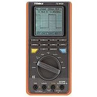
... The Meter Structure The Figure 2-1 shows the Meter structure. 1. USB Terminals 2. LCD Display 3. Functional Buttons 4. Rotary Switch 5. Power adaptor Input Terminals 6. 10A Input Terminal 7. mA µ A Input Terminals 8. COM Input Terminal 9. Other Input Terminals 12 Model 72-8400: OPERATING MANUAL Figure 2-1. Meter Structure ...
Page 14
... Model 72-8400: OPERATING MANUAL Functional Buttons The buttons activate features that augment the function selected with the rotary switch. The buttons are shown in Table 2-2. Figure 2-2. Functional Buttons Table 2-2. Functional Buttons Description Buttons Software functional buttons, details F1, F2, please refer to the below. ...
Page 15
... Press Set button to set the auto power Set off, backlight, contrast and beep Under scope mode, press Save/Cal to Save/Call store and recall data. Press Hold button to enter or exit hold Hold mode. 14 Model 72-8400: OPERATING MANUAL ...
Page 16
... Model 72-8400: OPERATING MANUAL Introduction Chapter 3 explains how to make measurements. You could turn the Meter off by turning to OFF position or set up the sleep mode from 1-30 minutes. Please ensure the Meter is not under sleep mode if you turn the Meter on without display. To avoid false readings, which could lead to possible electric shock or personal injury, replace the battery as soon as the battery indicator “ ...
Page 17
... The contrast level from 0 to 31. Press F4 to confirm, save and return. Press functional buttons to exit, the setting is kept, but will not save. The setting will be lost after power off. 16 Model 72-8400: OPERATING MANUAL F4: Set the beep feature, it can only be used under resistance, diode and continuity measurement. Beep ON ...
Page 18
... Model 72-8400: OPERATING MANUAL Turn the rotary switch to ACV, DCV, Hz, ACA or DCA range, the Meter displays digital reading (Multimeter mode). Press Mode to switch to waveform display (scope mode) as below Figure 4. When entering scope mode, time base is auto trace, the amplitude is manual set, you may need to re-set them. You could set the trigger level as well needed ...
Page 19
... Base Base Base < F1: increase the number of periods F2: decrease the number of periods. Rang F3: trigger point move left F4 F4: trigger point right move The auto set feature will be off when changing the measurement mode. Base > F4 Model 72-8400: OPERATING MANUAL ...
Page 20
... Model 72-8400: OPERATING MANUAL Press Trig button under scope mode, the corresponding function buttons: Trig Trig Auto/Norm/Shot Slop Rrise/Fall F1: move the trigger level up F2: move the trigger level down F3: select the trigger mode: auto, normal or single F4: slope adjustment: rise or fall iv. Waveform data save and recall ...
Page 21
... When measuring current signal, connect BNC black probe to the COM terminal and the red probe to mA terminal. Don’t connect the BNC probe to the 10A terminal. 20 Model 72-8400: OPERATING MANUAL B. Digital Multimeter Mode Warning To avoid personal injury or damage to the Meter from electric shock, please do not attempt to measure voltages higher than DC 1000V, AC 750V, although readings may be obtained ...
Page 22
... Model 72-8400: OPERATING MANUAL Figure 3-2. Voltages Measurement When measuring voltage, the corresponding functional buttons REL Rang Rang F1: toggle between F2: relative mode (REL will be displayed at the right bottom of the LCD when it is on) F3: select a range up F4: select a range down Note: After changing the measurement mode, the autoranging will be off automatically and the AUTO will be disappeared at the bottom left of the LCD ...
Page 23
... Never place the testing leads in parallel with any circuit or component when the leads are plugged into the current terminals. Turn off power to the circuit before test leads are connected in series to the return circuit to be tested. 22 Model 72-8400: OPERATING MANUAL ...
Page 24
... Model 72-8400: OPERATING MANUAL To measure AC µ µ A current, set up the Meter as Figure 3-3 and proceed as follows: Figure 3-3. µA Range Measurement 1. Insert the red test lead into the µ mA terminal and black test lead into the COM terminal. 2. Set the rotary switch to µ ...
Page 25
... To measure ACmA or DcmA currents, set up the Meter as Figure 3-4 and proceed as follows: Figure 3-4. mA Range Measurement 24 Model 72-8400: OPERATING MANUAL 1. Insert the red test lead into the µA mA terminal and black test lead into the COM terminal. 2. Set the rotary switch ...
Page 26
... Model 72-8400: OPERATING MANUAL To measure AC 10A or DC 10A current, set up the Meter as Figure 3-5 and proceed as follows: Figure 3-5. 10A Range Measurement 1. Insert the red test lead into the 10A terminal and black test lead into the COM terminal. 2. Set the rotary switch to A ...
Page 27
... LCD when it is on) F3: select a range up F4: select a range down 26 Model 72-8400: OPERATING MANUAL Note After changing the measurement mode, the autoranging will be off automatically and the AUTO will disappear from the bottom left of the LCD. If the value to be measured is unknown, use the ...
Page 28
... Model 72-8400: OPERATING MANUAL Warning To avoid possible damage to the Meter or to the devices under test, disconnect circuit power and discharge all the high-voltage capacitors before measuring resistance. To measure resistance, set up the Meter as shown in Figure 3-6 and follow the following procedure: Figure 3-6. Resistance Measurement ...
Page 29
... F3: select to a range up F4: select to a range down 28 Model 72-8400: OPERATING MANUAL Note When measuring low resistance, the test leads can add 0.1Ω to 0.2Ω of error to resistance measurement. To test the leads, touch the probe tips together and read the resistance of the leads. Take the reading obtained to subtract the resistance of the leads to get the final reading ...
Page 30
... Model 72-8400: OPERATING MANUAL Warning To avoid personal injury, please do not attempt to input voltages higher than 60V DC or 42V rms AC. To avoid damages to the Meter or to the devices under test, disconnect circuit power and discharge all the high-voltage capacitors before testing diodes. ...
Page 31
... F2 F1: toggle to continuity buzzer F2: relative mode 30 Model 72-8400: OPERATING MANUAL Note Connect the test leads to the proper terminals as said above to avoid error display. The LCD will display OL indicating either open circuit or wrong polarity connection. The unit of diode is volt (V), displaying the positive- connection voltage-drop value ...
Page 32
... Model 72-8400: OPERATING MANUAL Warning To avoid personal injury, please do not attempt to input voltage higher than 60V DC or 42V rms AC. To avoid possible damages to the Meter or to the devices under test, disconnect circuit power and discharge all the high-voltage capacitors before measuring continuity. ...
Page 33
... CONTINUITY REL F1 F2 F1: toggle to resistance measurement mode F2: relative mode 32 Model 72-8400: OPERATING MANUAL Note When continuity testing has been completed, disconnect the connection between the test leads and the circuit under test and remove the leads from the input terminals. ...
Page 34
... Model 72-8400: OPERATING MANUAL Warning To avoid personal injury, please do not attempt to input voltage higher than 60V DC or 42V rms AC. To avoid possible damages to the Meter or to the devices under test, disconnect circuit power and discharge all the high-voltage capacitors before measuring continuity. ...
Page 35
... When Hz or duty cycle measurement has been completed, disconnect the connection between the test leads and the circuit under test and remove the test leads from the input terminals 30Vrms; a 5Vrms Model 72-8400: OPERATING MANUAL ...
Page 36
... Model 72-8400: OPERATING MANUAL Warning To ensure accuracy, the Meter internally discharges the capacitor under test. To avoid damage to the Meter or to the equipment under test, disconnect circuit power and discharge all high-voltage capacitors before measuring capacitance. To measure capacitance, set up the Meter as shown in Figure 3-10 and proceed as follows: Figure 3-10 ...
Page 37
... Meter and the test leads recommended to use as short as test lead carrying out measurement to reduce the effect of internal distributed capacitor. 36 Model 72-8400: OPERATING MANUAL When measuring capacitance, the corresponding functional buttons: Capacity REL F1 F2 ...
Page 38
... Model 72-8400: OPERATING MANUAL When using the Software, please refer to the Installation Guide of the included CD-ROM. Chapter 4 Using Software 37 ...
Page 39
... Turn the Meter to OFF when it is not in use. l Take out the battery when not using for a long time not use or store the Meter in a place of humidity, 38 Model 72-8400: OPERATING MANUAL Chapter 5 Maintaining The Test Tool high temperature, explosive, inflammable and strong magnetic field. ...
Page 40
... Model 72-8400: OPERATING MANUAL B. Replacing the Fuses 1.Remove the 2.Remove the 3.Install fuses with battery compartment case bottom Figure 5-1. Fuse Replacement Warning To avoid electrical shock or arc blast, or personal injury or damage to the Meter, use specified fuses ONLY in accordance with the following procedure. ...
Page 41
... C. Replacing the Battery Figure 5-2. Battery Replacement 40 Model 72-8400: OPERATING MANUAL Warning To avoid false readings, which could lead to possible electric shock or personal injury, replace the battery as soon as the battery indicator “ Make sure the test leads are disconnected from the circuit being tested before opening the case bottom. ...
Page 42
... Model 72-8400: OPERATING MANUAL Safety and Compliances Maximum Voltage between any Terminal and Grounding Certification Compliances Fused Protection for mA input terminal: Fused Protection for 10A input terminal: Refer to different range input protection voltage IEC 61010 CAT. II 1000V, CAT.III 600V overvoltage and double insulation standard F0.5AH/250V, ø ...
Page 43
... Physical Specifications Display (LCD) Operating Temperature Storage Temperature Relative Humidity Altitude Battery Type Electromagnetic Compatibility Dimensions ( Weight 42 Model 72-8400: OPERATING MANUAL Digital: 3999 count display ; updates 2-3 times / second C~40 C (32 F~104 -10 C~50 C (14 F~122 75 C~ -10 C~50 C. Operating: 2000m; Storage: 10000m. ...
Page 44
... Model 72-8400: OPERATING MANUAL General Specifications ( Digital Multimeter) Range Polarity Overloading Battery Deficiency General Specifications (Scope) Display Auto setting Overloading Memory USB Tilt Stand When it is under Multimeter mode, you could select either auto or manual ranging. Auto, negative polarity displays “-“ ...
Page 45
... AC Voltage Basic Accuracy DC Current AC Current Resistance Capacitance Frequency 44 Model 72-8400: OPERATING MANUAL 160 x 160 Monochrome When under multimeter mode, the Meter automatically selects best range Beeper sounds for resistance readings below threshold. Measure signal on or off time in %. Battery replaceable. Ranges / Description ...
Page 46
... Model 72-8400: OPERATING MANUAL Basic Specifications (Scope) Horizontal Sampling rate 40M per second Sampling rate / Scale 20 pixels Updating rate >5 Trigger types Free Run / Normal / Single Shot Timebase Range 100ns/div~5 sec /div (1-2-5) Timebase accuracy (0.1% + 1pix) Detailed Accuracy Specifications Accuracy: ([% of reading] + [number of least significant digits]), guarantee for 1 year. ...
Page 47
... B. AC Voltage Range Resolution 4V 1mV 40V 10mV 400V 100mV 750V 1V 46 Model 72-8400: OPERATING MANUAL Accuracy Overload Protection (0.8%+8) 1000V (0.1%+8) Accuracy Overload Protection 1000V (1%+15) (1.2%+15) Input Impedance Around 10MΩ (excluding waveform) Input Impedance Around 10MΩ ...
Page 48
... Model 72-8400: OPERATING MANUAL C. DC Current Range Resolution 400 µ A 0.1 µ A 4000 µ µ µ A 40mA 100 µ A 400mA 4A 1mA 10A 10mA Accuracy Overload Protection (1%+8) F0.5AH/250V, ø5×20mm (1.2%+8) F10AH/250V, ø5×20mm. (1.5%+8) (Continuous measurement 10 seconds and interval more than 15 minutes.) ...
Page 49
... Range Resolution 400 µ A 0.1 µ A 4000 µ µ µ A 40mA 100 µ A 400mA 4A 1mA 10A 10mA 48 Model 72-8400: OPERATING MANUAL Accuracy Overload Protection (1.5%+8) F0.5AH/250V, ø5×20mm (2%+8) F10AH/250V, ø5×20mm (2.5%+5) (Continuous measurement 10 seconds and interval more than 15 minutes.) ...
Page 50
... Model 72-8400: OPERATING MANUAL E. Resistance Range Resolution 400Ω 0.1Ω 4kΩ 1Ω 40kΩ 10Ω 400kΩ 100Ω 4MΩ 1kΩ 40MΩ 10kΩ F. Diode Test Range Resolution 1mV Accuracy Overload Protection (1.2%+5) (1%+5) 250VDC or AC rms (1.2%+5) (1.5%+5) ...
Page 51
... H. Frequency and Duty Cycle % Range Resolution 10Hz~10MHz 0.001Hz 0.1%~99.9% 0.1% 50 Model 72-8400: OPERATING MANUAL Overload Protection Remarks l The buzzer sounds when the test resistance is 10Ω. 250V The buzzer does not sound when the test resistance is 100Ω. Accuracy (0 ...
Page 52
... Model 72-8400: OPERATING MANUAL I. Capacitance Range Resolution 40nF 10pF 400nF 100pF 4 µ F 1nF 40 µ F 10nF 100 µ F 100nF Accuracy Under REL mode: (3%+10) (3%+8) (4%+8) Overload Protection 250V rms 51 ...
Page 53
... This operating manual is subject to change without notice. 52 Model 72-8400: OPERATING MANUAL ** END ** ...
Page 54
...