72-6860 TENMA, 72-6860 Datasheet
72-6860
Manufacturer Part Number
72-6860
Description
SIGNAL GENERATOR, PULSE, 10MHZ
Manufacturer
TENMA
Datasheet
1.72-6860.pdf
(1 pages)
Specifications of 72-6860
Signal Generator Type
Pulse
Bandwidth
10MHz
Supply Voltage Range
98.9V To 131.1V
External Height
140mm
External Width
220mm
External Depth
230mm
Output Voltage Max
10V
Lead Free Status / RoHS Status
na
Specifications
Each parameter is variable within 8 overlapping decade
ranges with a vernier providing continuously variable
control within each range.
Jitter: <0.1 %
Jitter: <0.1 %
Trigger, Gate
continuously at 0.1Hz to 10MHz.
Triggered
trigger pulses; pulse width determined by pulse width
controls. Trigger can be generated manually from front
Gated
0.1Hz to 10MHz pulse train, parameters set by period and
edge of gate input. Last pulse is completed at the end of
gating period. Gating signal can be generated manually
from front panel button.
Period, Pulse Width, Delay
Period
Range: 100nsec to 10sec (10MHz to 1Hz)
Pulse Width
Range: 50nsec to 5sec
Delay:
Range: 50nsec to 5sec
Run
Normal operational mode in which pulses are generated
DC to 10MHz pulse train in synchronism with external
panel button.
pulse width controls, starts synchronously with leading
!
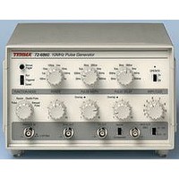
72-6860 10MHz Pulse Generator
3
4
2
5
1
6
7
10
8
9
One pulse is generated each period. The delay setting is
Gate/Trig Input
Signal Range: TTL threshold; max. input ±10V
Outputs
Complement Switch
General
Size: 140mm(H) x 220mm(W) x 230mm(D)
Operating Range: +5°C to 40°C; 20 %~80% R.H.
Storage Range: -40°C to 70°C
Safety: Complies with EN61010-1
Square wave
0.1Hz to 10MHz squarewave, frequency set by the period
controls. Pulse width and delay settings ignored.
A second pulse is generated after a delay set by the delay
controls; the delay is related to the leading edge of the first
A pulse is generated after a delay set by the delay controls;
the delay is related to the rising edge of the trigger signal.
50
Amplitude: Two switch selectable ranges of 0.1V~1.0V and
50 ) Adjustable within ranges by a single turn vernier.
Aberrations: Typically <5 % for output set at >20 % of range
Aux. Output
Sync Output
Amplitude: a positive going pulse at CMOS/TTL level.
Timing: Leading edge starts >20nsec before the TTL/50
output transition.
operating range ±14 % of nominal; 20VA max.
Weight: 1.6kg (3.5lb)
Pulse Modes
Normal Pulse
ignored.
Mark: Space Ratio: 1:1±10 %
Double Pulse
pulse.
Delayed Pulse
Inputs
Frequency Range: DC~10MHz
Min. pulse width: >30nsec
Input Impedance: Typically 10k
1V~10V from 50
Rise/Fall Times: Typically 10nsec into 50
Maximum 15ns
max. into 50
Duplicates 50
Duration: Typically 30nsec
Inverts the AUX and 50
Power: 115V AC nominal 50/60Hz, adjustable internally;
EMC: Complies with EN5508-1 and EN50082-1
Output
output but at a fixed CMOS/TTL level
50mV to 500mV and 500mV to 5V into
outputs
load.