50514 EMIT, 50514 Datasheet - Page 2
50514
Manufacturer Part Number
50514
Description
FULL TIME CONTINUOUS MONITOR, LED
Manufacturer
EMIT
Datasheet
1.50514.pdf
(4 pages)
Specifications of 50514
Meter Display Type
LED
External Height
11.4cm
External Width
6.4cm
External Depth
3cm
Weight
192g
Lead Free Status / RoHS Status
na
Available stocks
Company
Part Number
Manufacturer
Quantity
Price

Company:
Part Number:
505147-1
Manufacturer:
HARRIS
Quantity:
1


TB-6550 Page 2 of 4
Wave distortion technology can be referred to as “vector
impedance monitoring”. This description is valid as the
wave distortion technology measures the impedance at the
monitored banana jack and looks for changes in either the
capacitance or resistance of the circuit which includes the
wrist strap and its wearer. It uses filtering and time domain
sampling to filter out false signals caused by voltage offsets,
60 Hz fields and other electro-magnetic and electrostatic
interference.
In normal factory environments, and with persons whose
capacitance with respect to ground is within design limits
(5 feet tall 90 pound person to 6 foot 5 inch 250 pound
person), the Full Time Continuous Monitor cannot be
“fooled”. It will provide a reliable alarm only when the
wrist strap or work surface becomes dysfunctional or
unsafe according to accepted industry standards. The Full
Time Continuous Monitor is drift-free and designed to be
insensitive to the effects of squeezing or stretching the coil
cord.
ADVANTAGES OF WAVE DISTORTION AND
SINGLE-WIRE TECHNOLOGY
The EMIT Full Time Continuous Monitor allows the use of
any standard, single-wire wrist strap and coil cord. The
monitor / wrist strap / cord system life-cycle costs are by
far lower than alternative systems which require dual-wire
cords and special wrist straps. Dual-wire cords are
expensive and are the weak link of the system, the most
likely component to need replacement. Over a five year
period, this can make the dual-wire system three to five
times as expensive as a system utilizing single-wire wrist
straps and cords. See Calibration section on page 4 to
minimize life cycle costs.
The dictionary defines constant as uniform and unchanging,
and continuous as uninterrupted. None theless, some
dual-wire resistance monitors utilize a pulsed test current
and do not really provide continuous monitoring. For
example, during each 2.2 second pulse cycle of a leading
“constant” resistive monitor, electrical current is pulsed for
only 0.2 seconds followed by an unmonitored interval of 2
seconds. This leaves the user/wrist strap unmonitored for
over 90% of each cycle. Damaging static charges can easily
occur in the portion of the time in between the pulses. The
off period of 2 seconds equals 2 billion nanoseconds, and
“it takes only about 25 volts applied for 100 nanoseconds to
blow most memories or microprocessors”.* Some dual-wire
systems do not reliably meet all industry specifications, as
the cords may not meet the EOS/ESD S-1.0 paragraph
4.1.6 one to five pound “breakaway force” requirement for
operator safety.
By using the reliable wave distortion technology to
determine if the circuit is complete, there are no false
alarms. There is no need to adjust or tune the monitor to
a specific user or installation. The miniscule amount of
electrical current (less than 1 volt coil cord signal) required
to generate the waveform has never caused reported skin
irritation and is extremely safe for use in voltage sensitive
applications such as disk drive manufacturing.
*1981 article by Donald E. Frank - Electrical Overstress Electronic
Discharge Symposium Proceedings
EMIT - 3651 Walnut Avenue, Chino, CA 91710 • (909) 664-9980 • Fax (909) 627-7449 • Website: DescoEMIT.com
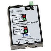
Figure 2. Full Time Continuous Monitor features and
components
Features and Components (See Figure 2)
A. Mat Ground: Grounds worksurface mat.
B. Mat Connection: Monitors worksurface mat.
C. I/O Signal Output: Can be used to output to a light
tower. (Relay required, see Figure 4)
While facing connector:
Pin 1: is on left, no connection
Pin 2: circuit ground
Pin 3: 24 VDC @ 1mA max
Pin 4: no connection
Pin 5: open collector, 1 mA max
PIn 6: no connection
D. IEC Power Cord Inlet: Connect the power cord here.
E. Mat Ground LEDs: When the green LED is lit, the work
surface mat is properly grounded. When the red LED is lit,
the work surface mat and/or electrical ground is not properly
grounded.
F. Operator Ground LEDs: When the green LED is lit, the
operator is properly grounded. When the red LED is lit, the
operator is not properly grounded.
G. Monitored Operator Jack: Where the operator inserts
the wrist cord banana plug.
D
C
A
I
© 2009 DESCO INDUSTRIES INC.
B
E
F
G
H
Employee Owned