50741 EMIT, 50741 Datasheet - Page 5
50741
Manufacturer Part Number
50741
Description
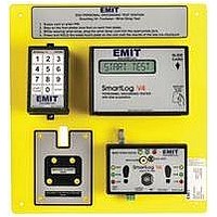
SmartLog V4 ESD/Static Protection Solid-State Touch Tester
Manufacturer
EMIT
Datasheet
1.50741.pdf
(6 pages)
Specifications of 50741
Meter Display Type
Digital
Meter Function
Testing Of ESD Grounding Items, Single Or Dual-Wire Wrist Straps & Footwear
Kit Contents
SmartLog V4, Wrist/Foot Strap Tester, Num Keypad, Foot Plate, Adapters, Asst Cables, Hardware
Rohs Compliant
NA
Lead Free Status / RoHS Status
na


TB-6572 Page 5 of 6
3. The RS-232 Interface is described by the Electronic
C. Connecting the SmartLog
NOTE: Both the SmartLog and computer should be turned off
during the following procedures.
Connecting One SmartLog V4 (See Figure 7)
1. Connect the Serial Adapter to the desired PC.
2. Connect one end of the provided RS-232 Non-inverted
3. Connect the other end of the RS-232 Non-inverted Data
NOTE: Ensure that the SmartLog ID is set to 00 and its
terminator jumper is left open.
Connecting More Than One SmartLog
(See Figure 8)
The following procedure provides an example on connecting 3
SmartLogs.
1. Connect the Serial Adapter to the desired PC.
2. Connect one end of the provided RS-232 Non-inverted
3. Connect the other end of the RS-232 Non-inverted Data
4. Set first SmartLog ID to 00.
5. Connect one end of a pair of 18 gauge wires to the clock
6. Connect the other end of the pair of 18 gauge wires to the
7. Set second SmartLog ID to 01.
8. Connect one end of another pair of 18 gauge wires to the
9. Connect the other end of the same pair of 18 gauge wires
10. Set second SmartLog ID to 02.
Industries Association (EIA) as EIA-232 or RS-232. Special
consideration should be used when installing the
communications cable. Keep a 3 feet separation distance
from any EMF source (power wires, fluorescent lights, etc).
The cable length shall not exceed 50 feet from PC to unit.
The EMIT
distance requirements exceed 50 feet.
Data Cable to the Serial Adapter.
Cable to port labeled “RS-232” on the SmartLog.
Data Cable to the Serial Adapter.
Cable to clock port labeled “RS-232” on the SmartLog.
port labeled “RS-485” on the first SmartLog.
clock port labeled “RS-485” on the second SmartLog.
clock port labeled “RS-485” on the second SmartLog.
to the clock port labeled “RS-485” on the third SmartLog.
50461
EMIT - 3651 Walnut Avenue, Chino, CA 91710 • (909) 664-9980 • Fax (909) 627-7449 • Website:
Ethernet Adapter should be used if
D. Mounting the SmartLog
Use the provided anchors and screws to mount the entire
SmartLog plate. Be sure to place the SmartLog at a height
where all operators can clearly see the display and perform
the necessary tests.
When the hardware installation has been completed, refer to
the
take you through the necessary steps to begin using your new
SmartLog system.
Troubleshooting
Problem: The host computer is not recognizing the SmartLog.
a. Verify that the cable from the computer to the SmartLog is
b. Verify that the communication setup on the clock is 9600
c. If there are more than 2 units, verify that their IDs are
d. Contact your local IT department to verify that the
e. Make sure that the SmartLog LED’s are blinking during
Contacts
USA
EMIT
3651 Walnut Ave
Chino, CA 91710
TEL: (909) 664-9980
FAX: (909) 627-7449
EUROPE
Charleswater
Unit 17, Millbrook Business Park, Sybron Way
Crowborough, East Sussex, TN6 3JZ, U.K.
TEL: +44 (0) 189 266 5313
FAX: +44 (0) 189 266 8838
properly connected. The cable should be flat non-inverted
(See Figure 7).
baud rate, parity ODD. Refer to the instructions on back of
SmartLog plate to enter configuration mode.
unique by entering the SmartLog configuration mode.
computer’s comport is working properly.
data transmission. If they are not blinking or remain on all
the time, please contact EMIT technical support at
(909) 664-9980 for further support.
TEAM5 Operation Manual
DescoEMIT.com
for installation. This manual will
© 2010 DESCO INDUSTRIES, INC.
Employee Owned