FLEX103 EVIDENCE, FLEX103 Datasheet - Page 24
FLEX103
Manufacturer Part Number
FLEX103
Description
FLEX Multibus RS232 Module
Manufacturer
EVIDENCE
Datasheet
1.FLEX103.pdf
(41 pages)
Specifications of FLEX103
Silicon Manufacturer
Microchip
Application Sub Type
FLEX Multibus RS232 Module
Kit Application Type
Communication & Networking
Kit Contents
Board, CD
Lead Free Status / RoHS Status
Lead free / RoHS Compliant


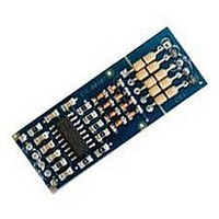
3.3.1 Thru Hole board
The board depicted in Figure
custom circuits that can be transparently interfaced with the FLEX Base Boards.
tronic components.
board. As can be seen in Figure 3.14, each pin on the piggybacking rows is connected
to a pin on the most wide board section. The remaining board surface is divided into
the most common pinhole patterns, such as:
3.3.2 Multibus
The Multibus board has been developed with the goal of providing various communica-
tion possibilities to the FLEX boards. The main idea of the Multibus board is to provide
The board makes several common pinholes available to the user, for connecting elec-
Patterns marked with “piggybacking” are pins which come from the piggybacked FLEX
1. standard 2.54 mm pattern;
2. standard 2.54 mm pattern with alternate phases, useful for, i.e., RJ45 and RS232
3. standard 1.27 mm pattern, useful for connecting typical SMD components;
4. standard 5.08 mm pattern, useful for, i.e., clamps;
connectors, etc.;
Figure 3.14: Thru Hole board.
3.14
is targeted to the development of small, homemade,
24
Related parts for FLEX103
Image
Part Number
Description
Manufacturer
Datasheet
Request
R

Part Number:
Description:
FLEX Light Base Board
Manufacturer:
EVIDENCE
Datasheet:

Part Number:
Description:
FLEX MultiBus Daughter Board
Manufacturer:
EVIDENCE
Datasheet:

Part Number:
Description:
FLEX Demo Daughter Board
Manufacturer:
EVIDENCE
Datasheet:

Part Number:
Description:
FLEX Full Base Board
Manufacturer:
EVIDENCE
Datasheet:

Part Number:
Description:
FLEX Blank Thru-Hole Daughter Board
Manufacturer:
EVIDENCE
Datasheet:

Part Number:
Description:
FLEX Multibus Ethernet Module
Manufacturer:
EVIDENCE
Datasheet:

Part Number:
Description:
FLEX Multibus RS422 Module
Manufacturer:
EVIDENCE
Datasheet:

Part Number:
Description:
FLEX Multibus CAN Module
Manufacturer:
EVIDENCE
Datasheet:

Part Number:
Description:
FLEX Multibus SPI Module
Manufacturer:
EVIDENCE
Datasheet:
Part Number:
Description:
FLEX Multibus Serial TTL Module
Manufacturer:
EVIDENCE
Datasheet:

Part Number:
Description:
Microcontroller & Microprocessor Development Tools Demo2 Pack
Manufacturer:
EVIDENCE
Datasheet:

Part Number:
Description:
Microcontroller & Microprocessor Development Tools Mini Kit
Manufacturer:
EVIDENCE
Datasheet:

Part Number:
Description:
Microcontroller & Microprocessor Development Tools Multibus Pack
Manufacturer:
EVIDENCE
Datasheet:

Part Number:
Description:
Microcontroller & Microprocessor Development Tools Demo2 suite
Manufacturer:
EVIDENCE

Part Number:
Description:
Microcontroller & Microprocessor Development Tools Fasttrack suite
Manufacturer:
EVIDENCE
Datasheet: