DB63R APEX PRECISION POWER, DB63R Datasheet

DC Brush Motor Driver Demo Board

DB63R

Manufacturer Part Number
DB63R
Description
DC Brush Motor Driver Demo Board
Manufacturer
APEX PRECISION POWER
Datasheet

Specifications of DB63R

Silicon Manufacturer
Cirrus Logic
Silicon Core Number
SA57
Kit Application Type
Power Management - Motor Control
Application Sub Type
DC Brushed Motor
Kit Contents
Board Docs
INTRODUCTION
The DB63R is designed to demonstrate the capabilities of the SA57 DC brush motor driver IC. This fully assembled
demonstration allows the user to directly control the speed and direction of the motor. An onboard circuit controls
the direction and provides four quadrant PWM signals to control the power outputs of the SA57. LEDs provide feed-
back for motor control status and fault indications. Provisions on the DB63R allow the user to bypass the onboard
control circuit and directly interface with the SA57 motor driver.
The DB63R demonstrates proper layout techniques for the
SA57 high current switching amplifier. The economical con-
struction uses only a two-sided PCB and allows the SA57 to
deliver peak currents of over 1kW.
THERMAL CONSIDERATIONS:
The SA57 is available in a surface mount package which
can deliver peak power of over 1kW. This presents an obvi-
ous and significant thermal challenge. The DB63R offers a
compact design which can deliver 17A peak current by using
a patent pending mounting technique. Mounting the SA57 in
an inverted fashion as shown in Figure 1 reduces the pro-
file height of the assembly and provides a direct interface
between the thermal tab of the PowerQuad package (pack-
age outline drawing HQ) and the small HS33 heatsink. The
DB63R assembly can dissipate 7-9W in still air at 25ºC ambi-
ent temperature, depending on the orientation of the heatsink
fins. To use the DB63R in higher power applications, use a
fan or mount a heatsink with larger thermal mass. Although
the SA57 is rated for operation from -25 to +85ºC, the other
components on the DB63R are limited to 0 to 70ºC ambient
temperature.
CIRCUIT OPERATION
The DB63R control circuit receives power via two terminal
block connections. The Vs connection supplies power to
drive the motor and must be above the under-voltage lock-
out threshold of the SA57, approximately 8.3V. The control
circuit requires 12V for proper operation a regulator on the
DB63R provides the 5V logic supply for the SA57. There are
no special considerations for sequencing the two supplies.
DB63RU
http://www.cirrus.com
Demonstration Board for the SA57-IHZ
P r o d u c t I n n o v a t i o n F r o m
Copyright © Cirrus Logic, Inc. 2009
(All Rights Reserved)
Figure  – Mounting Technique
PATENT PENDINg
APEX − DB63RUREVA
DB63R
DB63R
FEB 2009


Related parts for DB63R

DB63R Summary of contents

Page 1

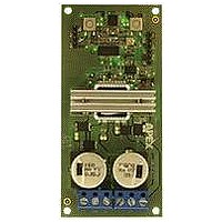
... Demonstration Board for the SA57-IHZ INTRODUCTION The DB63R is designed to demonstrate the capabilities of the SA57 DC brush motor driver IC. This fully assembled demonstration allows the user to directly control the speed and direction of the motor. An onboard circuit controls the direction and provides four quadrant PWM signals to control the power outputs of the SA57. LEDs provide feed- back for motor control status and fault indications ...

Page 2

... SA57 in all circumstances. The user must consider the worst case thermal and power dissipation conditions. Push-button switches 1 and 2 trigger latches (U4) for direction and enable control, respectively. Diodes D7 & D8 and resistors R24, 25, 29 & 30 provide a means of bypassing the DB63R control circuit. The 5V regulator, U3, pro- vides 5V to the SA57, the latches and the status LEDs. ...

Page 3

... Figure 3 – Schematic ENHANCINg & BYPASSINg THE DB63R CONTROL CIRCUIT: Connector J5 allows the user to bypass many of the manual control features of the DB63R. A signal generator can control the duty cycle with a 2.5 to 7.5V signal, overriding the control potentiometer. A rising 5V edge on pin connector J5 will toggle the Direction or Enable latches, respectively. By jumping resistors R24 & R25, the latches are bypassed completely and the logic signals on pins 3 & ...

Page 4

... Figure 4 shows the top and bottom layouts of the DB63R. Gerber files for the circuit board are available upon re- quest. ...

Page 5

... TB1-2 2. Apply 12V to Vctrl. LED 2 should light. 3. Apply voltage to Vs based on rated motor voltage, normally 12-48V. 4. Press ENABLE switch 3. LED 4 will light and motor should start. ORDERINg INFORMATION DB63R Demonstration Board includes one populated EVAL69R PCB and one SA57-IHZ sample. DB63RU P/N ...

Page 6

... LIABILITY, INCLUDING ATTORNEYS’ FEES AND COSTS, THAT MAY RESULT FROM OR ARISE IN CONNECTION WITH THESE USES. Cirrus Logic, Cirrus, and the Cirrus Logic logo designs, Apex and Apex Precision Power are trademarks of Cirrus Logic, Inc. All other brand and product names in this document may be trademarks or service marks of their respective owners. 6 DB63RU ...

Related keywords