CDB3318 Cirrus Logic Inc, CDB3318 Datasheet - Page 3
CDB3318
Manufacturer Part Number
CDB3318
Description
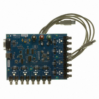
Eval Bd - 8-channel Digital Vol Cntrl
Manufacturer
Cirrus Logic Inc
Specifications of CDB3318
Main Purpose
Audio, Volume Control
Embedded
No
Utilized Ic / Part
CS3318
Primary Attributes
8 Single-Ended Analog Inputs and Outputs, USB or RS232 Interface
Secondary Attributes
Graphical User Interface
Description/function
Audio DSPs
Operating Supply Voltage
8 V to 9 V
Product
Audio Modules
Lead Free Status / RoHS Status
Contains lead / RoHS non-compliant
For Use With/related Products
CS3310
Lead Free Status / RoHS Status
Contains lead / RoHS non-compliant, Contains lead / RoHS non-compliant
Other names
598-1497


DS693DB2
1. SYSTEM OVERVIEW
The CDB4265 evaluation board is an excellent means for evaluating the CS3318 digitally controlled analog volume
control. Analog audio signal interfaces are provided, an on-board microcontroller and USB/RS-232 PC interface is
used for easily configuring the CS3318’s internal registers, and a USB cable is included for use with the FlexGUI
Windows configuration software.
The CDB3318 schematic set is shown in
1.1
1.2
1.3
1.4
Power (±8 V to ±9 V) must be supplied to the evaluation board through the red VA+ and green VA- binding
posts. An on-board regulator provides a 3.3 V supply to the digital circuitry. All voltage inputs must be ref-
erenced to the single black binding post ground connector (see the
WARNING: Please refer to the CS3318 data sheet for allowable voltage levels.
The CS3318 requires careful attention to power supply and grounding arrangements to optimize perfor-
mance.
shows the component placement.
the bottom layout. The decoupling capacitors are located as close to the CS3318 as possible. Extensive
use of ground plane fill in the evaluation board yields large reductions in radiated noise.
A complete description of the CS3318 is included in the CS3318 product data sheet.
The required configuration settings of the CS3318 are achieved via its control port registers, accessible
through the CS3318 tab of the Cirrus Logic FlexGUI software. A register-level configuration interface is pro-
vided on the Register Maps tab. See the
The evaluation board has been designed to allow interfacing with external systems via the headers J17,
J88, and J89.
The 15-pin, 3 column header, J17, provides bidirectional access to the CS3318’s SPI
digital control signals. The pins located in the column labeled “PC” connect to the on-board PC interface
circuitry, and those in the column labeled “In” connect directly to the CS3318’s digital control I/O pins. By
default, shunts are populated across these rows, connecting the PC interface to the CS3318’s digital control
I/O. To use an external digital control source, simply remove the shunts and connect a ribbon cable to the
“In” position. A single “GND” column for the ribbon cable’s ground connection is provided to maintain signal
integrity. Two unpopulated pull-up resistors are also available should the CDB3318 be required to provide
the pull-up function for the I²C bus.
The 10-pin, 2 column header, J89, provides bidirectional access to the CS3318’s I²C SDA and SCL signals,
as well as unidirectional output access to the CS3318’s AD0, ENOut, and MUTE signals. The SDA and SCL
signals are connected directly to their corresponding pins on the CS3318, as well as those on J17 described
above. The AD0, ENOut, and MUTE signals are re-driven versions of these signals as present directly on
their respective I/O pins on the CS3318. This header may be used to connect the serial control signals be-
tween 2 or more CDB3318’s (out of J89 on one and in to J17 on another) for multiple CS3318 I²C serial
control evaluation.
Power
Grounding and Power Supply Decoupling
CS3318 Analog Volume Control
External Control Headers
Figure 7 on page 9
provides an overview of the connections to the CS3318.
Figure 8
Figure 12 on page 14
“PC Software Control” section on page 5
through
Figure
shows the top layout.
10.
System Connections
Figure 13 on page 15
for more information.
Figure 11 on page 13
TM
table on
/I²C
CDB3318
®
and MUTE
page
shows
8).
3
Related parts for CDB3318
Image
Part Number
Description
Manufacturer
Datasheet
Request
R

Part Number:
Description:
Development Kit
Manufacturer:
Cirrus Logic Inc
Datasheet:
Part Number:
Description:
Development Kit
Manufacturer:
Cirrus Logic Inc
Datasheet:


Part Number:
Description:
High-efficiency PFC + Fluorescent Lamp Driver Reference Design
Manufacturer:
Cirrus Logic Inc
Datasheet:
Part Number:
Description:
Development Kit
Manufacturer:
Cirrus Logic Inc
Datasheet:
Part Number:
Description:
Development Kit
Manufacturer:
Cirrus Logic Inc
Datasheet:

Part Number:
Description:
Development Kit
Manufacturer:
Cirrus Logic Inc
Datasheet:
Part Number:
Description:
Development Kit
Manufacturer:
Cirrus Logic Inc
Datasheet:
Part Number:
Description:
Development Kit
Manufacturer:
Cirrus Logic Inc
Datasheet:
Part Number:
Description:
Development Kit
Manufacturer:
Cirrus Logic Inc
Datasheet:

Part Number:
Description:
EVALUATION BOARD FOR CS8427
Manufacturer:
Cirrus Logic Inc
Datasheet:

Part Number:
Description:
BOARD EVAL FOR CS8416 RCVR
Manufacturer:
Cirrus Logic Inc
Datasheet:

Part Number:
Description:
EVALUATION BOARD FOR CS8420
Manufacturer:
Cirrus Logic Inc
Datasheet:

Part Number:
Description:
KIT DEVELOPMENT EP9315 ARM9
Manufacturer:
Cirrus Logic Inc
Datasheet:

Part Number:
Description:
KIT DEVELOPMENT EP9302 ARM9
Manufacturer:
Cirrus Logic Inc
Datasheet: