56-725-005 Spectrum Control, 56-725-005 Datasheet - Page 2
56-725-005
Manufacturer Part Number
56-725-005
Description
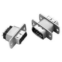
FILTERED D SUB ADAPTER, 25MALE-25FEMALE
Manufacturer
Spectrum Control
Series
700r
Datasheet
1.56-705-001.pdf
(22 pages)
Specifications of 56-725-005
Connector Type
Filtered D Sub Adapter
Convert From Connector
Standard D Sub
Convert From Positions
25
Convert From Gender
Plug
Convert To Connector
Standard D Sub
Lead Free Status / RoHS Status
Contains lead / RoHS non-compliant


Series 700
Specifications and Connector Ordering
Mechanical Specifications
Shell . . . . . . . . . . . . Zinc diecast, nickel plated
Insulators . . . . . . . . Glass-filled polyester,
Pin Contacts . . . . . . Copper alloy, 15 µ inches
Socket Contacts . . . . Copper alloy, 30 µ inches
Terminations . . . . . . Gold flash for PCB mount and solder
Ground Plane . . . . . Brass, solder plated
Grounding
Springs . . . . . . . . . . Beryllium copper, tin plated per
Operating
Temperature. . . . . . . -55°C to +125°C
Capacitors . . . . . . . . Proprietary barium titanate
Electrical Specifications
Current Rating . . . . 5 Amps
R.F. Current
Rating . . . . . . . . . . . 0.3 Amps
Contact
Resistance . . . . . . . . 10 milliohms maximum
UL Recognized. . . . . Under category of communication
Inductance on
PI Filters . . . . . . . . . ~ 860 nH between 100 kHz and 1 MHz
Solder cups accept up to a 20 gauge wire
Note:
For additional mechanical, electrical, and
environmental specifications, refer to page 201.
SPECTRUM CONTROL INC. • 8031 Avonia Rd. • Fairview, PA 16415 • Phone: 814-474-2207 • Fax: 814-474-2208 • Web site: www.spectrumcontrol.com
SPECTRUM CONTROL GmbH • Hansastrasse 6 • 91126 Schwabach, Germany • Phone: (49)-9122-795-0 • Fax: (49)-9122-795-58
. . . . . . . . . . . . . . . .
. . . . . . . . . . . . . . . .
. . . . . . . . . . . . . . . .
. . . . . . . . . . . . . . . .
. . . . . . . . . . . . . . . .
. . . . . . . . . . . . . . . .
. . . . . . . . . . . . . . . .
. . . . . . . . . . . . . . . .
. . . . . . . . . . . . . . . .
. . . . . . . . . . . . . . . . . . . . . .
150 µ inches (3.81 µm) min.
flammability UL94V-0
(0.38 µm) gold plated * over nickel
(0.76 µm) gold plated * over nickel
*
See pg. 169: Connector Options
cups. Solder dipped also available.
MIL-T-10727
ceramic formulations
circuit accessories, File #E149046
Heavier gold plating available upon request.
Ordering Your Connector
STEP 1: SELECTING THE FILTER
s
s
s
s
STEP 2: SELECTING THE CONNECTOR
s
s
s
s
STEP 3: SPECIFYING OPTIONS
s
s
s
Using the insert loss graphs on page 149
determine which filters provide the required
attenuation at the troublesome frequency, while
not affecting the signal frequency by more than
3 to 6 dB.
Choose the filter type, either feed-thru capacitor
or Pi. The Pi is generally considered better due
to its superior high frequency performance and
steeper curve. The feed-thru capacitor is lower
cost.
Select capacitance value.
Note the Spectrum letter designation for the
filter chosen from the table on page 149.
Turn to the appropriate size section.
(9, 15, 25, 37, 50)
Choose either pin contacts (plug) or socket
contacts (receptacle).
Choose the required termination type.
From the table on the appropriate connector
page, using the filter letter designation chosen
in step 1 above, select the part number.
Refer to page 172 for special options
including heavy gold plating, 4-40 mounting
threads, grounding brackets, hardware,
and others.
Most options are available within the standard
lead times.
Some options require a part number suffix,
while other combinations may require factory
assistance for part number assignment. If a
suffix is shown, add it to your selected part
number. If more than one option is needed,
consult with factory for part number
assignment.
150
Related parts for 56-725-005
Image
Part Number
Description
Manufacturer
Datasheet
Request
R

Part Number:
Description:
FILTERED D SUB ADAPTER, 25MALE-25FEMALE
Manufacturer:
Spectrum Control
Datasheet:
Part Number:
Description:
FILTERED D SUB ADAPTER, 25MALE-25FEMALE
Manufacturer:
Spectrum Control
Datasheet:

Part Number:
Description:
Power Line Filters Single Stage
Manufacturer:
Spectrum Control Inc.
Datasheet:
Part Number:
Description:
High Current Single Line Feed-thru Filters
Manufacturer:
Spectrum Control Inc.
Datasheet:
Part Number:
Description:
Switched And Fused Filtered Power Entry Modules
Manufacturer:
Spectrum Control Inc.
Datasheet:
Part Number:
Description:
Surface Mount Emi Filters
Manufacturer:
Spectrum Control Inc.
Datasheet:

Part Number:
Description:
(PSMx Series) Surface Mount EMI Filters
Manufacturer:
Spectrum Control
Datasheet: