9-140 Cinch Connectors, 9-140 Datasheet - Page 128
9-140
Manufacturer Part Number
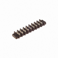
9-140
Description
BARRIER BLOCK 9POS .375"
Manufacturer
Cinch Connectors
Series
140r
Type
Wire to Boardr
Specifications of 9-140
Terminal Block Type
Barrier Block
Number Of Circuits
9
Number Of Positions
18
Pitch
0.375" (9.53mm)
Number Of Rows
2
Current
15A
Voltage
250V
Wire Gauge
16 AWG
Mounting Type
Chassis Mount or Panel Mount
Top Termination
Screws
Bottom Termination
Closed
Barrier Type
2 Wall (Dual)
Features
Flange
Color
Black
Operating Temperature
-55°F ~ 300°F
Material - Insulation
Phenol Formaldehyde (Phenolic)
Material Flammability Rating
UL94 V-1
Product
Barrier Terminal Blocks
Number Of Positions / Contacts
9
Current Rating
15 A
Voltage Rating
250 V
Wire Gauge Max (awg)
16
Current, Rating
15 A (Max.)
Length
4.032 in.
Material, Block
Phenolic
Material, Screw
Steel
Mounting Style
Bottom Mount
Plating, Screw
Nickel over Copper Flash
Screw Size
5-40 x 3⁄16
Temperature Range
-55 to +300 °F
Lead Free Status / RoHS Status
Lead free / RoHS Compliant
Lead Free Status / RoHS Status
Lead free / RoHS Compliant, Lead free / RoHS Compliant
Other names
9-140-P
9140-P
CBB109
9140-P
CBB109


D-subminiature Metal Shell and All Plastic
Solder Cup and IDC
T* Series
Insulator Material: Glass-filled polyester (black), UL 94 V-O rated
Connector Shell: Steel with zinc plating and yellow chromate finish or
Contact Material: Phosphor bronze (stamped)
Contact Plating: Gold flash or 30µin. gold in mating area and gold
Operating Temperature: -65°C to + 125°C
Shock: 50G peak per MIL-STD-202, Method 213, Condition G
Vibration: 12 cycles in three perpendicular directions @ 10-2000Hz, per
Moisture Resistance: 90-95% relative humidity @ 40°C for 96 hours per
Individual Contact Insertion and
Durability: 500 mating cycles
Call Toll Free: 1 (800) 323-9612
Insulation Resistance:
Separation Force (minimum/maximum): 0.7 oz./12 oz.
Withstanding Voltage:
Offered in 9, 15, 25, and 37 position plugs and sockets.
Available in Solder Cup and IDC (insulation displacement) terminations for discrete wire.
Offered with .120 mounting holes.
Approvals:
•
•
See pages 4-5 thru 4-10 for standard dimensions, contact arrangements, and panel
mounting specifications.
Contact Resistance:
UL Recognized - Files E170218 (UL1977) and E130965 (UL1863).
CSA Approved - File LR31996.
Current Rating:
MIL-STD-202, Method 204, Condition D
flash on the remainder. All over nickel.
tin plating (grounding indents on plug)
MIL-STD-202, Method 103
Minimum 1000V RMS @ sea level
3 Amps
2.7 milliohms maximum
5000 megohms maximum (initial);
1000 megohms (minimum) after
environmental testing
4-34
Related parts for 9-140
Image
Part Number
Description
Manufacturer
Datasheet
Request
R

Part Number:
Description:
BARRIER BLOCK 9POS .438"
Manufacturer:
Cinch Connectors
Datasheet:

Part Number:
Description:
BARRIER BLOCK 9POS .563"
Manufacturer:
Cinch Connectors
Datasheet:

Part Number:
Description:
CONN BARRIER BLOCK .375" 9 POS
Manufacturer:
Cinch Connectors
Datasheet:

Part Number:
Description:
CONNECTOR, DSUB FLTR, PLUG, 9POS, 1000PF
Manufacturer:
Cinch Connectors
Datasheet:

Part Number:
Description:
CONNECTOR, DSUB FLTR, RCPT, 9POS, 1000PF
Manufacturer:
Cinch Connectors
Datasheet: