1723 055 2101 HARTING, 1723 055 2101 Datasheet - Page 5
1723 055 2101
Manufacturer Part Number
1723 055 2101
Description
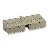
SOCKET, FEMALE, R/A, TYPE C, 55WAY
Manufacturer
HARTING
Series
HARBUSr
Datasheet
1.17_21_110_2101.pdf
(36 pages)
Specifications of 1723 055 2101
Connector Type
Rectangular Power
Gender
Receptacle
No. Of Contacts
55
No. Of Rows
5
Pitch Spacing
2mm
Connector Mounting
PCB
Contact Material
Copper Alloy
Svhc
No SVHC
Approval Bodies
IEC61076-4-101
Rohs Compliant
Yes
Lead Free Status / RoHS Status
Lead free / RoHS Compliant


Comparison of 2.0 mm systems
For many years board-to backplane connectors
were dominated by DIN connectors with a pitch of
2.54 mm. The advances of new designs in recent
years have migrated to 2.0 mm pitch connectors.
However, today there are three separate and non-
compatible 2.0 mm style connector families avail-
able on the market: Futurebus+ style, HDM
hard metric style.
Several years ago Futurbus+ and telecom applica-
tions standardised on a modular 2.0 mm connector
using of increments of 12 mm.These connectors are
currently undergoing IEC standardisation (IEC
61076-4-104). They are also specified for Industrial
PCI systems.
Another 2.0 mm connector specification available
today is commonly referred to as HDM
or VHDM. These connectors come in 22 mm and 46
mm increments.
This proprietary system is not standardised there-
fore, unable to provide a high degree of intermata-
bility.
For high speed applications like CompactPCI
hard-metric connector, such as har-bus
HARTING, was chosen. It is a modular 2 mm
connector using increments of 25 mm. Compact-
PCI
for 3U cards and five connectors (J1/P1 - J5/P5) for
6U cards. On 3U Eurocards two full size 50 mm
®
has specified two connectors J1/P1 and J2/P2
the 2.0mm hard metric system from HARTING
®
, HDM
®
HM from
®
®
®
plus
and
the
connectors will not assemble to a 100 mm card
height because of space needed for guide rails. The
type B connector is therefore shortened to 22 rows
or 44 mm length. J4/P4 and J5/P5 on 6U cards are
mirror images of J1/P1 and J2/P2 respectively. The
centre connector J3/P3 on 6U has 19 rows of pins.
This 19 row version is also used as the centre
connector J0/P0 on 6U VME boards.
The popular configuration of 2.0 mm hard metric
connectors are 5 rows of signal contacts and one or
two rows of outer shield or ground contacts. The
increase in pin-count over the popular DIN connec-
tor (IEC & EN 60603-2) is quite significant, 96 to 240
contacts. The enhanced or 5-row DIN compatible
connector (har-busâ 64) originated by HARTING,
has 160 contacts on a 2.54 mm pitch.
The IEC 61076-4-101 hard metric connector has
been designed for high-speed applications with
appropriate shielding options. It is specified for
CompactPCI
cations. Further standardisation is being developed
by VITA as a mechanical practice guide, VITA 30
Draft standard.
®
, VMEbus and proprietary appli-
5
Related parts for 1723 055 2101
Image
Part Number
Description
Manufacturer
Datasheet
Request
R


Part Number:
Description:
CODE COMB, DIN 41612 SHELL HOUSING D20
Manufacturer:
HARTING
Datasheet:

Part Number:
Description:
Harting Han Modular 2 Module female
Manufacturer:
HARTING
Datasheet:

Part Number:
Description:
Telecom & Ethernet Connectors Ethernet Switch HARTING mCon 3082-AD
Manufacturer:
HARTING
Datasheet:

Part Number:
Description:
Telecom & Ethernet Connectors ETHERNET SWITCH SCON 3063-AD
Manufacturer:
HARTING
Datasheet:

Part Number:
Description:
Telecom & Ethernet Connectors ETHERNET SWITCH ECON 2040-A
Manufacturer:
HARTING
Datasheet:
Part Number:
Description:
Ethernet Switch with 5 ports RJ Industrial / IP30
Manufacturer:
HARTING
Datasheet:

Part Number:
Description:
Telecom & Ethernet Connectors ETHERNET SWITCH ECON 3080-A1
Manufacturer:
HARTING
Datasheet:

Part Number:
Description:
Telecom & Ethernet Connectors ETHERNET SWITCH MCON 7050-A
Manufacturer:
HARTING
Datasheet:

Part Number:
Description:
Telecom & Ethernet Connectors ETHERNET SWITCH ECON 6050-A
Manufacturer:
HARTING
Datasheet:

Part Number:
Description:
Telecom & Ethernet Connectors ETHERNET SWITCH ECON 4080-B1
Manufacturer:
HARTING
Datasheet:
Part Number:
Description:
Manufacturer:
HARTING
Datasheet:

Part Number:
Description:
Telecom & Ethernet Connectors ETHERNET SWITCH SCON 3082-AD
Manufacturer:
HARTING
Datasheet: