142-0711-821 JOHNSON/EMERSON, 142-0711-821 Datasheet - Page 4
142-0711-821
Manufacturer Part Number
142-0711-821
Description
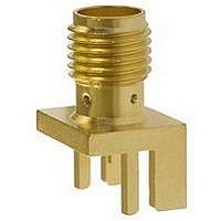
RF/COAXIAL, SMA JACK, STR, 50OHM, SOLDER
Manufacturer
JOHNSON/EMERSON
Datasheet
1.142-0701-801.pdf
(4 pages)
Specifications of 142-0711-821
Body Style
Straight Jack
Coaxial Termination
Solder
Contact Material
Beryllium Copper
Contact Plating
Gold
Frequency Max
12.4GHz
Connector Type
SMA Coaxial
Impedance
50ohm
Lead Free Status / RoHS Status
Lead free / RoHS Compliant
Available stocks
Company
Part Number
Manufacturer
Quantity
Price


SMA - 50 Ohm Connectors
End Launch Connectors - A Johnson Components
the board edge between the legs and soldering the legs and center con-
ductor to pads on the board. For optimum high frequency performance,
the connector to circuit board transition must be adjusted for low VSWR.
To compensate for the transition from coax to microstrip, trace widths “A”
and “B” must be adjusted based on circuit board thickness. When prop-
erly adjusted, this technique yields a low VSWR over a wide bandwidth.
experimentally to achieve low VSWR (typically less than 1.5 up to 18
GHz). The circuit board used for these tests was double-sided FR 4 with
1 oz. copper on both sides. The copper was left on the bottom of the
board to create a ground plane for the 50 Ohm microstrip structure. While
not all inclusive, these dimensions are given as reference information for
selected SMA End Launch connectors. Further adjustments may be
necessary depending upon the application. All dimensions are in inches.
SMA End Launch Specifications
ELECTRICAL RATINGS
Impedance: 50 Ohms
Frequency Range: 0-18 GHz
VSWR: Dependent upon application
Working Voltage (VRMS max.): 335 @ Sea Level, 85 @ 70K Feet
Dielectric Withstanding Voltage (VRMS min. at sea level): 1000
Corona Level (Volts min. at 70,000 feet): 250
Insulation Resistance: 5000 megohms min
Contact Resistance (milliohms max.): 3.0 Initial, 4.0 after environmental
RF High Potential Withstanding Voltage (VRMS min. tested at 4 and 7
MECHANICAL RATINGS
Engagement Design: MIL-C-39012, Series SMA
Engagement/Disengagement Force: 2 inch-pounds max.
Mating Torque: 7 to 10 inch-pounds
Coupling Proof Torque: 15 inch-pounds min.
Coupling Nut Retention: 60 pounds min.
Contact Retention Force: 6 lbs min. axial force, 4 inch-ounce min. torque
Durability: 500 cycles min.
The End Launch connector is attached to the circuit board by inserting
The tabulated dimensions "A", "B", "C", "D", and "E" were determined
MHz): 670
Tabulated Dimensions "A", "B", "C" and "D" are symmetrical about the center line
Johnson Components
TM
• P.O. Box 1732 • Waseca, MN 56093-0832 • 1-800-247-8256 • Fax: 507-833-6287 • www.johnsoncomponents.com
TM
Original
142-0701-801/806
142-0701-851/861
142-0701-871/876
142-0711-821/826
142-0711-871/876
142-0711-881/886
142-0701-881/886
Number
Part
ENVIRONMENTAL RATINGS:
(Meets or exceeds the applicable paragraph of MIL-C-39012)
Temperature Range: -65
Thermal Shock: MIL-STD-202, Method 107, Condition B
Corrosion: MIL-STD-202, Method 101, Condition B
Shock: MIL-STD-303, Method 213, Condition I
Vibration: MIL-STD-202, Method 204, Condition D
Moisture Resistance: MIL-STD-202, Method 106
MATERIAL SPECIFICATIONS
Bodies: Brass per QQ-B-626, gold plated* per MIL-G-45204 .00001” min.
Contacts: Male - brass per QQ-B-626, gold plated per MIL-G-45204 .00003”
Nut Retention Spring: Beryllium copper per QQ-C-533. Unplated
Insulators: PTFE fluorocarbon per ASTM D 1710 and ASTM D 1457
Mounting Hardware: Brass per QQ-B-626 or QQ-B-613, gold plated per
Female - beryllium copper per QQ-C-530, gold plated per MIL-G-45204
or nickel plated per QQ-N-290
min.
.00003” min.
MIL-G-45204 .00001” min. or nickel plated per QQ-N-290
Width
Surface Mount Versions Available!
Base
.375
.375
.375
.250
.375
.375
.375
.00005” min. nickel underplate barrier layer.
Board
Thick
*All gold plated parts include a
.062
.062
.062
.062
.047
.047
.031
o
to + 165
.103
.103
.103
.103
.083
.083
.050
"A"
o
C
CUSTOMER DRAWINGS AVAILABLE UPON REQUEST
.090
.090
.090
.070
.075
.075
.045
"B"
.250
.250
.250
.170
.250
.250
.250
"C"
INCHES (MILLIMETERS)
.440
.440
.440
.380
.440
.440
.440
"D"
.200
.200
.200
.165
.200
.200
.200
"E"
Related parts for 142-0711-821
Image
Part Number
Description
Manufacturer
Datasheet
Request
R


Part Number:
Description:
RF/COAXIAL, SMA JACK, STR, 50OHM, SOLDER
Manufacturer:
JOHNSON/EMERSON
Datasheet:

Part Number:
Description:
RF/COAXIAL, SMA JACK, R/A, 50OHM, SOLDER
Manufacturer:
JOHNSON/EMERSON
Datasheet:

Part Number:
Description:
RF/COAXIAL, SMA JACK, STR, 50OHM, SOLDER
Manufacturer:
JOHNSON/EMERSON
Datasheet:

Part Number:
Description:
RF/COAXIAL SMA BHD JACK STR 50OHM SOLDER
Manufacturer:
JOHNSON/EMERSON