GL02 MARATHON, GL02 Datasheet - Page 10
GL02
Manufacturer Part Number
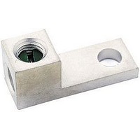
GL02
Description
TERMINAL, MECHANICAL LUG, 0.266IN, SCREW
Manufacturer
MARATHON
Datasheet
1.F30A3S.pdf
(150 pages)
Specifications of GL02
Connector Type
Lug, Mechanical
Termination Method
Screw
Stud/tab Size
0.266"
Wire Size (awg)
14-2/0
Contact Material
Aluminum
Contact Plating
Tin
Insulator Material
Non-Insulated
Lead Free Status / RoHS Status
Lead free / RoHS Compliant


R
Specifications:
Ordering Code:
30 and 60 Amp - 250 Volt
Marathon Special Products fuse holders comply to new harmonized fuse holder
standard 4248. Please refer to www.marathonsp.com for the latest updates.
Datasheets available at marathonsp.com
Class H & K Fuse Panels
•
•
•
•
•
•
•
•
•
•
Base, General Purpose Phenolic, 150
Patented Cool-Clip
Clip, Copper Alloy, Tin Plated
Reinforcing Member Available
Bus Bars are Available with 2/0 - #14 AWG or
250 kcmil - #6 Wire Ranges
Consult Customer Service for Special Requirements
UL Recognized File No. IZLT2.E35113
CSA Certified File No. LR21455
RoHS Compliant
S = Wire Binding Screw
B = Box Connector #2 - 14 CU
P = SEMS Pressure Screw
Q = .250 Male Quick Connect
C = Combination of the Above
0 = 60 Amps All Poles
1 = 30 Amps All Poles
2 = 30,60 Any Combination
3 = 30, 60, 60 Any Combination
Reinforcing Member
Amp Rating of Poles
Load Termination
#6 - 14 CU
(consult Customer Service)
Class H Fuse Distribution Panels
H
®
Design
Number of Poles 2, 3, 4, 5 or 6
4
o
C (UL RTI)
0
9
B
Code Same As Load Termination. Omit if
line Termination is Same as Load (S, B, P,
Q or C).
1 = Special Bussing (consult Cust. Service)
2 = Poles Bussed by Pairs
3 = Poles Bussed by Threes
4 = Poles Bussed by Fours
RH40Q2L
RH42C2F
Bussing Arrangements
Line Terminations
2
OR
F=Front L=Lateral
Entry of Bus Bar
(Only if Bussed)
L
Related parts for GL02
Image
Part Number
Description
Manufacturer
Datasheet
Request
R

Part Number:
Description:
MARATHON SPECIAL PRODUCTS
Manufacturer:
MARATHON
Datasheet:

Part Number:
Description:
TERMINAL BLOCK, BARRIER, 8POS, 18-6AWG
Manufacturer:
MARATHON
Datasheet:

Part Number:
Description:
TERMINAL BLOCK, BARRIER, 12POS, 18-6AWG
Manufacturer:
MARATHON
Datasheet:

Part Number:
Description:
TERMINAL BLOCK, BARRIER, 4POS, 18-4AWG
Manufacturer:
MARATHON
Datasheet: