A97F8625 GE, A97F8625 Datasheet - Page 12
A97F8625
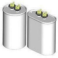
Manufacturer Part Number
A97F8625
Description
CAPACITOR PP FILM 10UF, 1.5KV, CASE G
Manufacturer
GE
Datasheet
1.A97F8625.pdf
(18 pages)
Specifications of A97F8625
Capacitor Dielectric Type
Polypropylene
Capacitance Tolerance
± 10%
Voltage Rating
1500VDC
Capacitor Case Style
CAN
No. Of Pins
2
Capacitor Mounting
Panel
Capacitance
10µF
Lead Free Status / RoHS Status
Contains lead / RoHS non-compliant


Application Data for SCR and Snubbers Capacitors
This Application Note is designed to allow users
to select the correct capacitor for two common
conditions encountered in power electronic circuits:
For applications that do not fit into either of these
categories, please contact your GE sales
representative for assistance.
To select the correct capacitor proceed as
follows:
1.
2.
3.
If the “corrected” RMS current value is equal to or
greater than the RMS current of the application, the
capacitor is suitable. If not, a capacitor with a higher
current rating must be selected. This can be done
by choosing a higher voltage capacitor. Note that the
All-FilmA 97F8600 series has the highest current
ratings.
Note: In no case should the actual RMS current
exceed the limit of the capacitor terminals .
Example No. 1
Capacitance:
Voltage:
Ambient Temperature: 65 °C
Current Pulsewidth = 166 µs
Peak Voltage
RMS Current
For use with capacitor series:
(a) Sinusoidal waveform
(b)
(1) Microfarad value required
(2)
(3)
(4) Current pulsewidth
(5) Capacitor ambient temperature.
Select a capacitor with the correct
Apply the correction factors on the opposite
page for Current Pulsewidth and Ambient
Temperature to the 55 °C RMS Current
Rating of the selected capacitor.
Determine the following:
capacitance and a peak voltage equal to or
greater than the application voltage.
A97F8600/ A97F8700
Squarewave.
Peak voltage
RMS current
= 2p x 3000 x 10 x 10 -6 x 200
= 200 x Ö2 = 283 Volts
= 37.7 A
10 mF
200 Vac RMS 3 kHz
Sinewave
© 2000 GE Company
11
The A97F8672 has a current rating of 136 A.
Applying the correction factors for a 166 ms
pulsewidth and a 65 °C ambient:
Example No. 2
Capacitance:
Voltage:
Ambient T emperature: 65°C
Current Pulsewidth
The A97F8671 is rated 86 amps which becomes
80.6A with the correction factors. This is more
than adequate. Again, note the 60-A terminal
limitation.
Example No. 3
Capacitance:
Voltage:
Frequency:
Rise Time:
Fall Time:
Ambient Temperature: 65°C
Peak Voltage
I peak =
I rms = 313
Current Pulsewidth = 60 ms
The A97F8673 has a peak voltage rating of 600
V and a current rating of 235 A. The correction
factor for 65°C is 0.75, and for a 60 µs pulsewidth
it is 0.90. Thus its current rating in this application is
235 x 0.80 x 0.90 = 158.6 A; adequate for the
application. Again, note the 60A terminal limitation.
Peak Voltag
RMS current
RMS current rating = 136 x 0.56 x 0.75
Note the terminal limit of 60 amps.
This capacitor is satisfactory.
CDV
0.64t
Ö
60 x 10
-6
=
=
x 200 = 32.4 A
5 µF
60 Vac RMS 16.6 kHz
Sinewave
= 60 Ö2 = 85 V
= 2 p x 16,600 x 5 x 10
= 31.3 A
= 3 0 µs
20 µF
600 Vpeak unidirectional
squarewave
200 Hz
60 µs
60 µs
600 V
20 x 10
0.64 x 60 x 10
= 57.1 A
-6
x 600
-6
= 313 A
-6
x 60
Related parts for A97F8625
Image
Part Number
Description
Manufacturer
Datasheet
Request
R


Part Number:
Description:
CISCO 3600 1 1000BT DAUGHTERCARD EHTERSWCH NM
Manufacturer:
CISCO SYSTEMS

Part Number:
Description:
NTC Thermistor
Manufacturer:
GE Sensing
Datasheet:
Part Number:
Description:
GLASS PASSIVATED MEDIUM-SWITCHING JUNCTION RECTIFIER
Manufacturer:
GE [General Semiconductor]
Datasheet:
Part Number:
Description:
GLASS PASSIVATED FAST SWITCHING RECTIFIER
Manufacturer:
GE [General Semiconductor]
Datasheet:
Part Number:
Description:
Silicon Planar Zener Diodes
Manufacturer:
GE [General Semiconductor]
Datasheet:
Part Number:
Description:
ZENER DIODES
Manufacturer:
GE [General Semiconductor]
Datasheet:
Part Number:
Description:
GE PNP PWER BJT
Manufacturer:
NJSEMI [New Jersey Semi-Conductor Products, Inc.]
Datasheet:
Part Number:
Description:
ZENER DIODES
Manufacturer:
GE [General Semiconductor]
Datasheet: