BFC233620154 Vishay, BFC233620154 Datasheet - Page 16
BFC233620154
Manufacturer Part Number
BFC233620154
Description
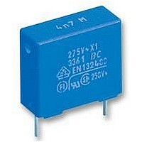
CAPACITOR, CLASS X2 0.150UF CAPACITOR, CLASS X2 0.150UF
Manufacturer
Vishay
Series
2222336r
Datasheet
1.BFC233620103.pdf
(17 pages)
Specifications of BFC233620154
Capacitance
150NF
Voltage Rating, Ac
275V
Voltage Rating, Dc
630V
Capacitor Dielectric Type
POLYPROPYLENE
Tolerance,
20%
Tolerance, -
20%
Temp, Op.
ROHS COMPLIANT
Tolerance
20 %
Voltage Rating
275 Volts
Termination Style
Radial
Lead Spacing
15 mm
Dimensions
6 mm W x 17.5 mm L x 12 mm H
Operating Temperature Range
0 C to + 105 C
Product
Metallized Polypropylene Suppression Capacitors
Lead Free Status / Rohs Status
Details


www.vishay.com
16
MKP 336 2 X2
Vishay BCcomponents
SUB-CLAUSE NUMBER AND
TEST
SUB-GROUP C4
4.15 Charge and discharge
4.15.1 Initial measurements
4.15.3 Final measurements
SUB-GROUP C5
4.16 Radio frequency
characteristic
SUB-GROUP C6
4.17 Passive flammability
SUB-GROUP C7
4.18 Active flammability
Class B
CONDITIONS
10 000 cycles
Charged to 435 Vdc
Discharge resistance:
Tangent of loss angle:
For C ≤ 1 µF at 10 kHz
For C > 1 µF at 1 kHz
Tangent of loss angle
Insulation resistance
Resonance frequency
Bore of gas jet: Ø 0.5 mm
Fuel: Butane
Test duration for actual volume V in mm³:
V ≤ 250: 10 s
250 < V ≤ 500: 20 s
500 < V ≤ 1750: 30 s
V > 1750: 60 s
One flame application
20 cycles of 2.5 kV discharges on the test
capacitor connected to U
Capacitance
Capacitance
R
=
---------------------------------------------- -
1.25
Interference Suppression Film Capacitors
For technical questions, contact: RFI@vishay.com
435 Vdc
×
C dU dt
(
45.0°
MKP Radial Potted Type
⁄
)
Rac
~ 8 mm
12 mm
PERFORMANCE REQUIREMENTS
¦ΔC/C¦ ≤ 10 % compared to values measured in
4.15.1.
Increase of tan δ:
≤ 0.008 for: C ≤ 1 µF or
≤ 0.005 for: C > 1 µF
Compared to values measured in 4.15.1.
≥ 50 % of values specified in section “Insulation
Resistance” of this specification
≥ 0.9 times the value as specified in section
“Resonant Frequency” of this specification
After removing test flame from capacitor, the
capacitor must not continue to burn for more than
10 s. No burning particle must drop from the
sample.
The cheese cloth around the capacitors shall not
burn with a flame.
No electrical measurements are required.
Document Number: 28120
Revision: 08-Oct-08
Related parts for BFC233620154
Image
Part Number
Description
Manufacturer
Datasheet
Request
R

Part Number:
Description:
357-036-542-201 CARDEDGE 36POS DL .156 BLK LOPRO
Manufacturer:
Vishay
Datasheet:
Part Number:
Description:
357-036-542-201 CARDEDGE 36POS DL .156 BLK LOPRO
Manufacturer:
Vishay
Datasheet:
Part Number:
Description:
357-036-542-201 CARDEDGE 36POS DL .156 BLK LOPRO
Manufacturer:
Vishay
Datasheet:
Part Number:
Description:
357-036-542-201 CARDEDGE 36POS DL .156 BLK LOPRO
Manufacturer:
Vishay
Datasheet:
Part Number:
Description:
357-036-542-201 CARDEDGE 36POS DL .156 BLK LOPRO
Manufacturer:
Vishay
Datasheet:
Part Number:
Description:
357-036-542-201 CARDEDGE 36POS DL .156 BLK LOPRO
Manufacturer:
Vishay
Datasheet:
Part Number:
Description:
357-036-542-201 CARDEDGE 36POS DL .156 BLK LOPRO
Manufacturer:
Vishay
Datasheet:
Part Number:
Description:
357-036-542-201 CARDEDGE 36POS DL .156 BLK LOPRO
Manufacturer:
Vishay
Datasheet:
Part Number:
Description:
357-036-542-201 CARDEDGE 36POS DL .156 BLK LOPRO
Manufacturer:
Vishay
Datasheet:
Part Number:
Description:
357-036-542-201 CARDEDGE 36POS DL .156 BLK LOPRO
Manufacturer:
Vishay
Datasheet:
Part Number:
Description:
357-036-542-201 CARDEDGE 36POS DL .156 BLK LOPRO
Manufacturer:
Vishay
Datasheet:
Part Number:
Description:
357-036-542-201 CARDEDGE 36POS DL .156 BLK LOPRO
Manufacturer:
Vishay
Datasheet:
Part Number:
Description:
357-036-542-201 CARDEDGE 36POS DL .156 BLK LOPRO
Manufacturer:
Vishay
Datasheet:
Part Number:
Description:
357-036-542-201 CARDEDGE 36POS DL .156 BLK LOPRO
Manufacturer:
Vishay
Datasheet:
Part Number:
Description:
357-036-542-201 CARDEDGE 36POS DL .156 BLK LOPRO
Manufacturer:
Vishay
Datasheet: