M34C156K100BZSS Vishay, M34C156K100BZSS Datasheet
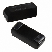
CAPACITOR, TANT, 15UF, 100V

M34C156K100BZSS

Manufacturer Part Number
M34C156K100BZSS
Description
CAPACITOR, TANT, 15UF, 100V
Manufacturer
Vishay
Series
M34r
Type
Hermetically Sealedr

Specifications of M34C156K100BZSS

Capacitance Tolerance
± 10%
Voltage Rating
100VDC
Esr
3.5ohm
No. Of Pins
2
Operating Temperature Range
-55°C To +85°C
Capacitance
15µF
Peak Reflow Compatible (260 C)
No
Leaded Process Compatible
No
Voltage - Rated
100V
Tolerance
±10%
Esr (equivalent Series Resistance)
3.500 Ohm
Operating Temperature
-55°C ~ 125°C
Mounting Type
Surface Mount
Package / Case
0803 (2108 Metric)
Size / Dimension
0.835" L x 0.315" W (21.20mm x 8.00mm)
Height
0.295" (7.50mm)
Manufacturer Size Code
C
Features
Wet Tantalum
Capacitor Case Style
C
Esr Frequency
120Hz
Svhc
No SVHC (15-Dec-2010)
Rohs Compliant
No
Termination Style
SMD/SMT
Product
Tantalum Wet SMD/SMT Molded Case
Lead Free Status / RoHS Status
Contains lead / RoHS non-compliant
Lead Spacing
-
Lead Free Status / Rohs Status
No
Other names
718-1700
M34
Vishay
PERFORMANCE CHARACTERISTICS
Operating Temperature: - 55 °C to + 85 °C
(To + 125 °C with voltage derating.)
Capacitance Tolerance: At 120 Hz, + 25 °C, ± 20 %
standard, ± 10 %
DC Leakage Current (DCL Max.): At + 25 °C and above:
Leakage current shall not exceed the values listed in the
Standard Ratings Tables.
Life Test: Capacitors are capable of withstanding a 2000 h
life test at a temperature of + 85 °C or + 125 °C at the
applicable rated DC working voltage.
Following life test:
1. DCL, measured at + 85 °C rated voltage, shall not be in
excess of the original requirement.
2. The equivalent series resistance shall not exceed 150 %
of the initial requirement.
3. Change in capacitance shall not exceed 10 % from the
initial measurement.
* Pb containing terminations are not RoHS compliant, exemptions may apply
www.vishay.com
1
MODEL
Packaging: The use of formed plastic trays for packing bulk components is standard.
ORDERING INFORMATION
M34
Wet Tantalum Capacitors Surface Mount, Molded Case
Ratings
CODE
Codes
CASE
Case
Table
See
and
C
number of zeros
CAPACITANCE
picofarads. The
first two digits
expressed in
figures. The
third is the
significant
to follow
are the
This is
826
For technical questions, contact:
CAPACITANCE
TOLERANCE
K = ± 10 %
M = ± 20 %
M
DC VOLTAGE RATING
three-digit block, zeros
volts. To complete the
This is expressed in
precede the voltage
AT + 85 °C
rating.
125
wettants@vishay.com
FEATURES
• Terminations:
• Very high capacitance, 10 µF to 470 µF
• Very low ESR
• High ripple current capability
• Low DCL
• Model M34 wet tantalum electrolytic chip capacitors
• Compliant to RoHS directive 2002/95/EC
APPLICATION NOTES
a) No continuous reverse voltage permissible.
b) Transient reverse voltage surges are acceptable under
c) The peak of the applied AC ripple and the applied DC
100 % tin (RoHS compliant) terminations
available
6 V to 125 V, - 55 °C to + 125 °C
incorporate the advantages of all the varieties of
electrolytic capacitors and eliminate most of the
disadvantages. These units have a transient reverse
voltage capability and a higher ripple current capability
than any other electrolytic type with similar combinations of
capacitance and case size.
the following conditions:
The peak reverse voltage does not exceed 1.5 V and the
peak current times the duration of the reverse transient
does not exceed 0.05 A. In addition, the repetition
frequency of the reverse voltage surge is less than 10 Hz.
voltage must not exceed the DC voltage rating of
the capacitor.
AND PACKAGING
(RoHS compliant),
B = Std, tin/lead,
TERMINATION
A = 100 % tin
bulk
bulk
B
standard
RELIABILITY
Z = Non-ER
LEVEL
tin/lead
Z
Document Number: 40106
Revision: 11-Aug-09
(SnPb),
S = Std
TEMP
S
S = Std
ESR
L

Related parts for M34C156K100BZSS

M34C156K100BZSS Summary of contents

Page 1

... DC voltage rating of the capacitor. M 125 CAPACITANCE DC VOLTAGE RATING TOLERANCE ° ± This is expressed ± volts. To complete the three-digit block, zeros precede the voltage rating. wettants@vishay.com standard tin/lead (SnPb TERMINATION RELIABILITY TEMP AND PACKAGING LEVEL A = 100 % tin Z = Non- Std ...

Page 2

... Lead Lead Sn/Pb Sn/Pb (Pb) - free (Pb) - free 217 °C 183 °C 150 °C 100 °C For technical questions, contact: wettants@vishay.com P P (MIN 3.0 6.0 ± 0 MAX MAX. s Lead Lead Sn/Pb Sn/Pb (Pb) - free (Pb) - free 200 °C 150 ° 150 www.vishay.com M34 Vishay (MIN ...

Page 3

... This includes transcients and ripple at the highest line voltage. The surge voltage is 115 % of rated DC working voltage. The capacitors shall be capable of withstanding a 2000 h life test at 85 °C at rated voltage wettants@vishay.com MAX. CAPACITANCE CHANGE (%) ° °C + 125 ° ...

Page 4

... The terminations must be solderable per the Mil Standard. All terminals shall be permanently secured internally and externally, as applicable. All external joints shall be welded. The part marking shall include Vishay name, trademark, capacitance, voltage, date code and lot symbol. C (NOM.) D (NOM.) [4.0] [6 ...

Page 5

... Vishay product could result in personal injury or death. Customers using or selling Vishay products not expressly indicated for use in such applications their own risk and agree to fully indemnify and hold Vishay and its distributors harmless from and against any and all claims, liabilities, expenses and damages arising or resulting in connection with such use or sale, including attorneys fees, even if such claim alleges that Vishay or its distributor was negligent regarding the design or manufacture of the part ...

Related keywords