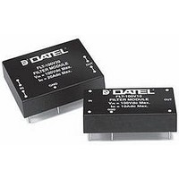
FLT-100V10 Murata Power Solutions Inc, FLT-100V10 Datasheet - Page 4

FLT-100V10
Manufacturer Part Number
FLT-100V10
Description
POWER LINE FILTER, 10A
Manufacturer
Murata Power Solutions Inc
Datasheet
1.FLT-100V10.pdf
(7 pages)
Specifications of FLT-100V10
Input Voltage Min
0VDC
Peak Reflow Compatible (260 C)
No
Output Current
10A
Output Current 1
10A
Leaded Process Compatible
No
Input Voltage Max
100VDC
Mounting Type
PC Board Surface Mount
Lead Free Status / RoHS Status
Contains lead / RoHS non-compliant
Figure 2 shows a typical connection diagram for the attenuation of both
differential and common-mode noise when used as an input fi lter to a DC/DC
converter, while Figure 3 shows the recommended layout. Noise introduced
into circuits is dependent upon the characteristics of the load, layout and
grounding techniques, and cabling. Since application requirements differ, the
fi nal circuit confi gurations may be best obtained through empirical testing.
CHASSIS
in Front of a DATEL BWR-5/6-3.3/7-D12 Dual-Output DC/DC Converter
GND
2
2
1
1
2
1
SHIELD PLANE
+INPUT
–INPUT
Figure 2. Typical Application Using FLT-100V Series Filters
Figure 3. Typical Layout Using FLT-100V Series Filters
FLT-100V
3
3
3
FILTER
FLT-100V10
GND
FILTER
TOP VIEW
OUTPUT
OUTPUT
in Front of a DC/DC Converter
C2
C1
4
4
5
5
4
5
C3
+INPUT
–INPUT
C1
DC/DC
CONVERTER
C3
C2
4
2
CASE
1
CONVERTER
www.murata-ps.com
DC/DC
OUTPUT
RETURN
+V1
+V2
OUT
OUT
C5
C4
C6
C4
C6
8
7
6
5
C
Conducted Emissions Performance
Conducted Emissions standards imposed by governing agencies must be
met at the system level, not the component level. Many designers, however,
apply these standards to the individual components to assure system-level
compliance. The following performance graphs show the Conducted Emis-
sions improvements seen when using an FLT-100V series fi lter in series with
the input lines of a typical switching DC/DC converter. Conducted Emis-
sions testing was performed within a EMCO 5305 GTEM test cell utilizing
EMCO automated EMC test software. Signal levels were measured from an
EMCO 3825/2 Line Impedance Stabilization Network (LISN) using a Hewlett
Packard 8568B spectrum analyzer with an attached Hewlett Packard 85650A
quasi-peak adapter in peak detection. Limits are based on FCC Part 15
Subpart J Class A and B, as well as EN 55022 Class A and B.
100
100
90
80
70
60
50
40
30
20
10
90
80
70
60
50
40
30
20
10
0
0
0.1
0.1
Filter Modules, 100Vdc, 10 Amp and 20 Amp
BWR-5/6-3.3/7-D12 Conducted Emissions
BWR-5/6-3.3/7-D12 Conducted Emissions
Technical enquiries email: sales@murata-ps.com, tel:
EN 55022 Class A Limit
EN 55022 Class A Limit
Using FLT-100V10 Filter
Differential/Common-Mode Filters
1.0
1.0
Frequency (MHz)
Frequency (MHz)
Conducted Emissions
Conducted Emissions
MMP_FLT10-20-Series.B03 Page 4 of 7
FLT Series
EN 55022 Class B Limit
EN 55022 Class B Limit
10.0
10.0
+1 508 339 3000


