B82477G4223M EPCOS Inc, B82477G4223M Datasheet - Page 3
B82477G4223M
Manufacturer Part Number
B82477G4223M
Description
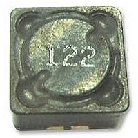
INDUCTOR, POWER, 22UH
Manufacturer
EPCOS Inc
Series
B82477-G4r
Specifications of B82477G4223M
Inductance Tolerance
± 20%
Dc Resistance Max
0.038ohm
Dc Current Rating
3.6A
Core Material
Ferrite
Inductor Case Style
SMD
No. Of Pins
2
Svhc
No SVHC (18-Jun-2010)
Dc Current Max
3.6A
Inductance
22µH
Rohs Compliant
Yes
Lead Free Status / RoHS Status
Lead free / RoHS Compliant
Available stocks
Company
Part Number
Manufacturer
Quantity
Price

Company:
Part Number:
B82477G4223M000
Manufacturer:
EPCOS
Quantity:
60 000
Part Number:
B82477G4223M000
Manufacturer:
EPCOS/爱普科斯
Quantity:
20 000


1.4.2
In order to be able to choose the correct EMC measures, we need to know the characteristics of the
interferences, how they are propagated and the mechanisms by which they are coupled into the cir-
cuit. In principle, the interferences can also be classified according to their range
quencies, it can be assumed that the interference only spreads along conductive structures, at high
frequencies only by means of electromagnetic radiation. In the MHz frequency range, the term cou-
pling is generally used to describe the mechanism.
Analogously, conducted interference on lines at frequencies of up to several hundred kHz are main-
ly symmetrical ( differential mode ), at higher frequencies, they are asymmetrical ( common mode ).
This is because the coupling factor and the effects of parasitic capacitance and inductance between
the conductors increase with frequency.
X capacitors and single chokes are suitable as suppression measures for the differential mode com-
ponents. Where asymmetrical, i.e. common-mode interference has to be eliminated, current-com-
pensated chokes and Y capacitors are mainly used, the prerequisite for this being, however, a well-
designed, EMC-compliant grounding and wiring system.
The categorization of types of interference and suppression measures and their relation to the fre-
quency ranges is reflected in the frequency limits for interference voltage and interference field
strength measurements.
10
Fig. 2
General Technical Information
_
2
Unsymmetrical interference:
– This term is used to describe interference on a single line, relative to the reference potential
(fig.
Differential mode
1c)
Pc ch.
X cap
Characteristics of interferences
Line
Frequency range overview
Pc ch. = Iron powder core chokes, but also all single chokes/ X cap = X capacitors
Cc ch. = Current-compensated chokes / Y cap = Y capacitors
10
_
1
Interference voltage
Cc ch.
10
Y cap
Common mode
0
Coupling
Ground
10
1
11
Field strength
Shielding
10
Field
Field
2
04/00
f
SSB1558-D
MHz 10
3
Interference
characteristic
Interference
propagation
Remedies
Max. ratings
(fig.
2). At low fre-
Related parts for B82477G4223M
Image
Part Number
Description
Manufacturer
Datasheet
Request
R

Part Number:
Description:
INDUCTOR POWER 47UH 2.5A SMD
Manufacturer:
EPCOS Inc
Datasheet:

Part Number:
Description:
INDUCTOR POWER 10UH 5.4A SMD
Manufacturer:
EPCOS Inc
Datasheet:

Part Number:
Description:
INDUCTOR POWER 4.7UH 6.8A SMD
Manufacturer:
EPCOS Inc
Datasheet:

Part Number:
Description:
INDUCTOR POWER 100UH 1.7A SMD
Manufacturer:
EPCOS Inc
Datasheet:

Part Number:
Description:
INDUCTOR POWER 1000UH .55A SMD
Manufacturer:
EPCOS Inc
Datasheet:


Part Number:
Description:
CAP .15UF 63V METAL POLY
Manufacturer:
EPCOS Inc
Datasheet:
