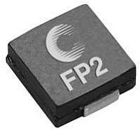
FP2-S100-R COILTRONICS, FP2-S100-R Datasheet - Page 2

FP2-S100-R
Manufacturer Part Number
FP2-S100-R
Description
HIGH FREQUENCY INDUCTOR, 100NH, 39A, 15%
Manufacturer
COILTRONICS
Datasheet
1.FP2-D100-R.pdf
(4 pages)
Specifications of FP2-S100-R
Inductance Tolerance
± 15%
Dc Resistance Max
240µohm
Dc Current Rating
39Arms
Core Material
Ferrite
No. Of Pins
2
Inductor Type
High Frequency
Saturation Current
22A
Inductance
100nH
Lead Free Status / RoHS Status
Lead free / RoHS Compliant
Available stocks
Company
Part Number
Manufacturer
Quantity
Price
Part Number:
FP2-S100-R
Manufacturer:
COOPER
Quantity:
20 000
Mechanical Diagrams
Single Conductor
Dual Conductor
Notes: (1) Marking SXXX = S: Single Conductor Style, DXXX = D: Dual
Packaging Information
(S or V)XXX
TOP VIEW
Ao=6.6mm
Bo=7.1mm
Ko=3.2mm
Ko=5.2mm
(FP2-S200
DXXX
TOP VIEW
& FP2V)
(2) All Dimensions are in millimeters unless otherwise specified.
1
2
yww
yww
6.70
Max
Conductor Style, XXX - last three digits of part number. Date Code:
yww = y: Last Digit of year, ww: week of year.
6.70
Max
1
2
4
3
7.20
Max
7.20
Max
Ko
SIDE VIEW
(4x)
SIDE VIEW
Bo
1.5 Dia
min.
1.00 ref.
1.0 min.
Ao
FRONT VIEW
(2x)
2.0
1.25 (2x)
4.0
12.0
ref.
1.30 ref.
3.00 mm
FRONT VIEW
(2x)
Max
3.0 ref.
A
7.50
1.5 Dia.
+0.1/-0.0
A
4.50
(2x)
1.30 ref.
1
2
2
mm Max
1
(2x)
Height
Series Mode
3.00
(4x)
Direction of Feed
0.50 (typ)
PCB PAD LAYOUT
7.50
(3) For parallel mode operation, connect terminals 1 to 4 and 2 to 3 on
4
3
1.75
PCB (use Single Conductor PCB Layout) For series mode operation,
connect terminals 2 to 4 on PCB (Dual Conductor Model).
PCB PAD LAYOUT
1
2.50 (2x)
2
1.50
7.5
©
7.50
1
2
6.50
(4x)
2 Winding Mode
+/-0.3
16.0
3.00
(4x)
0.50
2.50 (2x)
Low Profile Inductors
4
3
2.50 (2x)
ACTUAL SIZE
FLAT-PAC’S
2
1
(Surface Mount)
SCHEMATIC
Winding 1
2
1
FLAT-PAC™
SCHEMATIC
Winding 2
3
4


