11A21B10 Vishay, 11A21B10 Datasheet
11A21B10
Specifications of 11A21B10


Related parts for 11A21B10

11A21B10 Summary of contents
Page 1
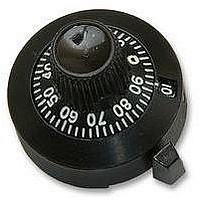
... FINISH AND OTHER FEATURES 11. Satin chrome, black markings 21. Black chrome, white markings 31. Brushed chrome, black markings 41. Satin chrome, white markings A SHAFT DIAMETER FINISH For technical questions, contact: sfer@vishay.com 1 / " shaft adapter 8 Single counter type wheel and a graduated circular dial registering a total count of 11 turns ...
Page 2
... Vishay product could result in personal injury or death. Customers using or selling Vishay products not expressly indicated for use in such applications their own risk and agree to fully indemnify and hold Vishay and its distributors harmless from and against any and all claims, liabilities, expenses and damages arising or resulting in connection with such use or sale, including attorneys fees, even if such claim alleges that Vishay or its distributor was negligent regarding the design or manufacture of the part ...