29 0006 ALPS, 29 0006 Datasheet - Page 3
29 0006
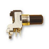
Manufacturer Part Number
29 0006
Description
POTENTIOMETER, 10KA
Manufacturer
ALPS
Series
RK09r
Datasheet
1.29_0006.pdf
(5 pages)
Specifications of 29 0006
Track Resistance
10kohm
Track Taper
Log (Audio)
No. Of Turns
1
Resistance Tolerance
± 20%
Voltage Rating
20V
Power Rating
50mW
No. Of Gangs
1
Resistor Element
RoHS Compliant
Adjustment Type
Horizontal
Potentiometer Mounting
PCB
Rohs Compliant
Yes


SYHB
ELECTRICAL
MECHANICAL
ENDURANCE
NOTE
4.Residual
2. Rated power
3. Rated voltase
5. SI id ins noise
7. Withstand voltage: More
8. Taper
4. Starting toruoue
6. Insulation resistance
2. Operation toroue
3. Shaft end atop strength
5. Resistance to soldering heat
1. Total resistance : 10k Q ±20K
6. Play of
7. Eccentricity of
8. Robustness of
I.Overall
9. Robustness of shaft against side thrust
2. Operatins temperature '--10 C~+60 C.
1. The items except above men]ioned, iterns shall meet or exceed JIS C 6443.
OATE
After soldering
I.-Rt)tat tonal
evidence of ooor contact
Physical damages as a result of the test.
The resistor shall
and a side thrust of 250 sf-cm at the end of the shaft shall be applied,
The eccentricity of
center of
The shaft shall withstand against end thrust of not less than 5 Kgf for
3 seconds.
The shaft shall withstand against side thrust of not
3 seconds on the end of
then the total Play of the shaft shall not exceed
after mounting the resistor by soldering.
The rated voltage shall be the voltage of 0. C.
rated voltage exceeds the maximum working voltage given in the
however,
(commercial
(dissi oat ion), and be obtained Iron the fol lowing formula.
Where
Maximum working voltase : 50 V A. C.
APPO
rotational
shaf t
CHKD
the mounting Position.
the maximum working voltage of
resistance
frequency .effective value )
E = /FF (V)
E : Rated voltase
P : Rated bower (dissioation)
R : Nominal total resistance to)
life
between
shaft against end thrust
DSCD
(Less than 300 C and quicker than 3 seconds)
shaft
:
'• 0. 05 W
:
:
: A
be mounted by soldering the mounting
the root of shaft shall not exceed 0. 35ttm against the
angle
APPO.
Sep. 13.'96
S. Aiiatia
Less than 100 mV measured
T
:
the shaft at right angles to the axis of the shaft
:
SPECIFICATIONS
between resistance element and terminals,
5. 000 cycles mi n.
term. 142.
Greater than 100 Mn measured by D. C. 250V.
than I minute with an application of A. C. 250
between
: 260 15
:
= 3 Kof-cm MIN.
:
I0~80 sf-cm
100 sf-cm MAX.
CHKD.
Set. 13.'96
H. Satot)
-*
ALPS ELECTRIC CO., LTD.
,
(V)
.
terminals
term. 2&3
3. Storage temperature :~30 C~+70 C.
ISailot
Set. 13. '96
0SCD.
t—r
the following shall
corresponding to the rated power
:
.
:
20 V D. C.
(W)
or A. C.
TITLE
DOCUMENT
0. 5 x I / 20 mm d-d.
W1 0 I I 7 57M
by method of
:
I
less than 4 Kof-cm for
3000
lees on the panel,
NO.
I
When the obtained
there shall be no
max.
be
I
following.
the rated voltage.
JIS C 6443.
or any
Related parts for 29 0006
Image
Part Number
Description
Manufacturer
Datasheet
Request
R

Part Number:
Description:
POTENTIOMETER, 10KB
Manufacturer:
ALPS
Datasheet:
Part Number:
Description:
POTENTIOMETER, 10KA
Manufacturer:
ALPS
Datasheet:

Part Number:
Description:
POTENTIOMETER, 10KB
Manufacturer:
ALPS
Datasheet:
Part Number:
Description:
POTENTIOMETER, 100KB
Manufacturer:
ALPS
Datasheet:
