3310H-1-102L Bourns Inc., 3310H-1-102L Datasheet - Page 16
3310H-1-102L
Manufacturer Part Number
3310H-1-102L
Description
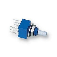
POTENTIOMETER, 1K
Manufacturer
Bourns Inc.
Series
3310Hr
Datasheet
1.3310H-1-102L.pdf
(54 pages)
Specifications of 3310H-1-102L
Track Resistance
1kohm
Track Taper
Linear
No. Of Turns
1
Resistance Tolerance
± 20%
Voltage Rating
200V
Power Rating
250mW
No. Of Gangs
2
Svhc
No SVHC (15-Dec-2010)
Resistor Element
RoHS Compliant
Potentiometer Mounting
PCB
Rohs Compliant
Yes


218
Standard Resistance Range
Resistance Tolerance..................................................(B, D,& G tapers) ±20% ............................................(A, C, & F tapers) ±10%
Independent Linearity .................................................(B & E tapers) ±5% ...................................................(A & H tapers) ±5%
Absolute Minimum Resistance ...................................2 ohms maximum .....................................................2 ohms maximum
Continuity....................................................................Maintained for full mechanical angle ........................Maintained for full mechanical angle
Effective Electrical Angle ............................................240° ±5%..................................................................240° ±6°
Contact Resistance Variation......................................±1% ..........................................................................±1% or 3 ohms (whichever is greater)
Theoretical Resolution ................................................Essentially infinite......................................................Essentially infinite
Dielectric Withstanding Voltage ..................................MIL-STD-202, Method 301.......................................MIL-STD-202, Method 301
Insulation Resistance (500 VDC).................................1,000 megohms minimum ........................................1,000 megohms minimum
Power Rating At 70°C (Voltage Limited By Power
Dissipation or 350 VAC, Whichever Is Less)
Roll-on/Roll-off............................................................(B & E tapers) 0.25% maximum................................(A & H tapers) 0.5% maximum
Operating Temperature..........................................+1°C to +125°C ...................................................+1°C to +125°C
Storage Temperature Range.......................................-55°C to +125°C .......................................................-55°C to +125°C
Temperature Coefficient
Vibration (Single Section)............................................15G ...........................................................................15G
Shock (Single Section)................................................30G ...........................................................................30G
Load Life .....................................................................1,000 hours ...............................................................1,000 hours
Rotational Life (No Load) ............................................100,000 cycles..........................................................100,000 cycles
Moisture Resistance ...................................................MIL-STD-202, Method 103, Condition B..................MIL-STD-202, Method 103, Condition B
Running Torque (Non-Locking Bushings)
Running Torque (Locking Bushings) ...........................0.2 to 4.0 oz.-in. (0.14 to 2.82 Ncm) .........................0.2 to 4.0 oz.-in. (0.14 to 2.82 Ncm)
Shaft Locking Torque with Locknut
Stop Strength..............................................................1/4” (6.35mm) and 1/8” (3.18mm) shafts - ...............1/4” (6.35mm) and 1/8” (3.18mm) shafts -
Mechanical Angle .......................................................300° ±5° ....................................................................300° ±5°
Weight (Single Section) ...............................................21 grams maximum ..................................................21 grams maximum
Terminals.....................................................................Printed circuit terminals or J-Hooks .........................Printed circuit terminals or J-Hooks
Marking .......................................................................Manufacturer’s trademark, wiring diagram, date code and resistance, manufacturer’s part number
For dimensional drawings see page 222.
For ordering information see page 224.
Initial Electrical Characteristics
Environmental Characteristics
Mechanical Characteristics
Linear Tapers (A, B, E, & H)......................................(B & E) 1K ohms to 1 megohm..................................(A & H) 50 ohms to 1 megohm
Audio Tapers (C, D, F, G, S, & T) .............................(D, G, S, & T) 1K ohms to 1 megohm........................(C & F) 1K ohms to 1 megohm
Sea Level .................................................................1,500 VAC minimum .................................................1,500 VAC minimum
70,000 Feet ..............................................................500 VAC minimum ....................................................500 VAC minimum
+70°C Single Section Assembly ..............................(B & E tapers) 0.5 watt ..............................................(A & H tapers) 2 watts
+70°C Multiple Section Assembly ...........................(B & E tapers) 0.5 watt/section .................................(A & H tapers) 1 watt/section
+125°C .....................................................................0 watt ........................................................................0 watt
Over Storage Temperature Range ...........................±1,000PPM/°C..........................................................±150PPM/°C
Voltage Ratio Shift ...................................................±5% maximum .........................................................±5% maximum
Total Resistance Shift ..............................................±2% maximum .........................................................±2% maximum
Total Resistance Shift ..............................................±10% maximum .......................................................±5% maximum
Total Resistance Shift ..............................................(B & E tapers) 10 ohms or ±12% maximum ............10 ohms or ±10% maximum
Total Resistance Shift ..............................................(B & E tapers) ±10% maximum ................................±5% maximum (all tapers)
Insulation Resistance (500 VDC)..............................100 megohms minimum ...........................................100 megohms minimum
Single Section ..........................................................0.2 to 1.5 oz.-in. (0.14 to 1.06 Ncm) .........................0.2 to 1.5 oz.-in. (0.14 to 1.06 Ncm)
Dual Section.............................................................0.2 to 1.5 oz.-in. (0.14 to 1.06 Ncm) .........................0.2 to 1.5 oz.-in. (0.14 to 1.06 Ncm)
Triple Section ...........................................................0.5 to 2.0 oz.-in. (0.35 to 1.41 Ncm) .........................0.5 to 2.0 oz.-in. (0.35 to 1.41 Ncm)
Quadruple Section ...................................................0.5 to 2.0 oz.-in. (0.35 to 1.41 Ncm) .........................0.5 to 2.0 oz.-in. (0.35 to 1.41 Ncm)
@ 10 in-lb. (B & E Bushings) ....................................20 oz-in. ....................................................................20 oz-in.
Each Additional Section...........................................6 grams maximum ....................................................6 grams maximum
1
1
1
NOTE: Model 81/82 performance specifications do not apply to units subjected to printed circuit board cleaning procedures.
1
At room ambient: +25°C nominal and 50% relative humidity nominal, except as noted.
Conductive Plastic Element
(E, S, & T tapers) ±10%
(D, G, S & T tapers) 0.25 watt
(D, G, S & T tapers) 0.25 watt/section
(whichever is greater)
(D, G, S & T tapers) ±20% maximum
(D, G, S & T tapers) ±20% maximum
7/8” (19.81mm) shaft -2 in.-lb. ( 22.6 Ncm) min.
(D & S tapers) 0.1% maximum CCW end
(G & T tapers) 0.1% maximum CW end
(D & S tapers) 0.5% maximum CW end
(G & T tapers) 0.5% maximum CCW end
81/82 - 5/8” Square Single-Turn Conductive Plastic
Features
4 in.-lb. (45.19 Ncm) min.
Metal shaft and bushing
Consistent, smooth quality feel
Up to 4 sections available
Cermet Element
(H taper) ±5%
(C & F tapers) 1 watt
(C & F tapers) 0.5 watt/section
(C taper) 0.1% maximum CCW end
(F taper) 0.1% maximum CW end
(C taper) 1.0% maximum CW end
(F taper) 1.0% maximum CCW end
(whichever is greater)
4 in.-lb. (45.19 Ncm) min.
7/8” (19.81mm) shaft -2 in.-lb. ( 22.6 Ncm) min.
Specifications are subject to change without notice.
Related parts for 3310H-1-102L
Image
Part Number
Description
Manufacturer
Datasheet
Request
R

Part Number:
Description:
POT 20K OHM 9MM SQ PLASTIC
Manufacturer:
Bourns Inc.
Datasheet:
Part Number:
Description:
POT 10K OHM 9MM SQ PLASTIC
Manufacturer:
Bourns Inc.
Datasheet:

Part Number:
Description:
POT 100K OHM 9MM SQ PLASTIC
Manufacturer:
Bourns Inc.
Datasheet:
Part Number:
Description:
RES,Conductive Plastic,1KOhms,20+/-% Tol,3838-Case
Manufacturer:
Bourns Inc.
Datasheet:
Part Number:
Description:
PANEL CONTROL-9MM SQ
Manufacturer:
Bourns Inc.
Datasheet:
Part Number:
Description:
PANEL CONTROL-9MM SQ
Manufacturer:
Bourns Inc.
Datasheet:
Part Number:
Description:
Panel Mount Potentiometers 9mm 1Kohms Slotted Dual Cup
Manufacturer:
Bourns Inc.
Datasheet:
Part Number:
Description:
Panel Mount Potentiometers 9mm 1Mohms Slotted Dual Cup
Manufacturer:
Bourns Inc.
Datasheet:
Part Number:
Description:
Panel Mount Potentiometers 9mm 1Mohms Slotted Dual Cup W/switch
Manufacturer:
Bourns Inc.
Datasheet:
Part Number:
Description:
Panel Mount Potentiometers 9mm 1Kohms Slotted Dual Cup
Manufacturer:
Bourns Inc.
Datasheet:

Part Number:
Description:
Manufacturer:
Bourns, Inc.
Datasheet:
Part Number:
Description:
11mm Potentiometer
Manufacturer:
Bourns, Inc.
Datasheet: