ST7ETB104 Vishay, ST7ETB104 Datasheet - Page 2
ST7ETB104
Manufacturer Part Number
ST7ETB104
Description
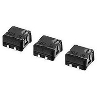
POT, TRIM, 100KOHM, 3TURN, 20%, SMD
Manufacturer
Vishay
Series
ST7r
Datasheet
1.ST7ETB104.pdf
(4 pages)
Specifications of ST7ETB104
Track Resistance
100kohm
No. Of Turns
3
Resistance Tolerance
± 20%
Power Rating
250mW
Potentiometer Mounting
SMD
Temperature Coefficient
± 100ppm/°C
Adjustment Type
Top
Lead Free Status / RoHS Status
Lead free / RoHS Compliant


■
■
Reflow profile for soldering heat evaluation
■ Specifications are subject to change without notice. Specifications in this catalog are for reference. The formal specification sheets will be submitted upon request.
Top adjustment
Pieces in package
Nominal resistance range
Resistance tolerance
Power ratings
Resistance law
Maximum input voltage
Maximum wiper current
Effective electrical turn
End resistance
C.R.V.
Operating temp. range
Temp. coefficient
Insulation resistance
Dielectric strength
Net weight
Adjustment
position
LIST OF PART NUMBERS
ELECTRICAL CHARACTERISTICS
250
200
150
100
( C)
50
A (
B (
Shape of terminal
180 C
150 C
J-hook
Gull wing
)
)
DC200 V or power rating, whichever is smaller
Pre Heating Zone
100 mA or power rating, whichever is smaller
100
Peak : 250
Heating time
Reflow : two times maximum
Over 230 C
1 % or 2 , whichever is greater
1 % or 3 , whichever is greater
90 30 s
50
1000 M minimum (DC500 V)
0.25 W (70 °C) 0 W (125 °C)
500 pcs./reel
Taping (reel)
~ 1 M : 100 10
ST-7ETA
ST-7ETB
30 10 s
: 250 10
+5
0
Approx. 0.25 g
AC600 V, 60 s
50
C
Linear law
55 ~ 125 °C
Form of packaging
2.5 turns
Soldering Zone
20 %
~ 1 M
-6
/°C maximum
-6
/°C maximum
50 pcs./pack
Plastic bag
ST-7EA
ST-7EB
〉
<Nominal resistance values>
※ The above part numbers are all available with the respective combination of
※ Verify the above part numbers when placing orders.
※ Taping specification is not sold separately and must be purchased in reel units.
■
■
Mechanical turn
Operating torque
Mechanical stop
Rotational life
Thrust to shaft
Solderability
Shear (Adhesion)
Substrate bending
Pull-off strength
Thermal shock
Humidity
Shock
Vibration
Load life
Low temp. operation
High temp. exposure
Immersion seal
Soldering heat
10 k
50
<Nominal resistance values> (Fig. 1).
Test item
MECHANICAL CHARACTERISTICS
ENVIRONMENTAL CHARACTERISTICS
100
20 k
200
50 k
SURFACE MOUNT TRIMMERS
Flow : 260 3 °C as the temperature in a pot of
molten solder, immersion from head of terminal to
backside of board, 5 ~ 6 s, two times maximum
Reflow : Peak temperature 255 °C
(Please refer to the profile below.)
Manual soldering:350 10 °C, 3 ~ 4 s
10 ~ 2000 Hz, 3 directions, 12 times each
100 k
6 directions for 3 times each
500
65 ~ 125 °C (0.5 h), 5 cycles
Amplitude 1.52 mm or
Acceleration 196 m/s
70 °C, 0.25 W, 1000 h
COPAL ELECTRONICS
10 ~ 65 °C (80 ~ 98 %),
Test conditions
981 m/s
125 °C, 250 h
10 cycles, 240 h
200 k
85 °C, 60 s
1 k
55 °C, 2 h
Width 90 mm, bend 3 mm, 5 s, 1 time
100 cycles [ Δ R/R ≦
2
, 6 ms
500 k
2 k
5 mN·m {51 gf·cm} maximum
5 N {0.51 kgf} minimum
245 3 °C, 2 ~ 3 s
5 N {0.51 kgf} 10 s
5 N {0.51 kgf} 10 s
1 M
2
5 k
,
Clutch action
Δ R/R:Change in total resistance
S.S. :Setting stability
3 turns
Fig. 1
No leaks (No continuous bubbles)
{ }
Specifications
[ Δ R/R ≦ 2 %]
[ Δ R/R ≦ 2 %]
[ Δ R/R ≦ 1 %]
[ Δ R/R ≦ 3 %]
[ Δ R/R ≦ 2 %]
[ Δ R/R ≦ 3 %]
[ Δ R/R ≦ 1 %]
(2
[S.S. ≦ 1 %]
[S.S. ≦ 1 %]
[S.S. ≦ 1 %]
[S.S. ≦ 2 %]
[S.S. ≦ 2 %]
:
Reference only
ST-7
3 %)]
Related parts for ST7ETB104
Image
Part Number
Description
Manufacturer
Datasheet
Request
R

Part Number:
Description:
Trimmer Resistors - Multi Turn
Manufacturer:
Vishay
Datasheet:
Part Number:
Description:
Trimmer Resistors - SMD ST7ETB503
Manufacturer:
Vishay
Datasheet:

Part Number:
Description:
POT 20K OHM 7MM CERMET TOP SMD
Manufacturer:
Copal Electronics Inc
Datasheet:
Part Number:
Description:
POT 1.0K OHM 7MM CERMET TOP SMD
Manufacturer:
Copal Electronics Inc
Datasheet:
Part Number:
Description:
POT 100K OHM 7MM CERMET TOP SMD
Manufacturer:
Copal Electronics Inc
Datasheet:
Part Number:
Description:
POT 5.0K OHM 7MM CERMET TOP SMD
Manufacturer:
Copal Electronics Inc
Datasheet:

Part Number:
Description:
POT 1.0K OHM 7MM CERMET TOP SMD
Manufacturer:
Copal Electronics Inc
Datasheet:
Part Number:
Description:
POT 2.0K OHM 7MM CERMET TOP SMD
Manufacturer:
Copal Electronics Inc
Datasheet:
Part Number:
Description:
POT 5.0K OHM 7MM CERMET TOP SMD
Manufacturer:
Copal Electronics Inc
Datasheet:
Part Number:
Description:
POT 5K 7MM CERM SQ MT SMD
Manufacturer:
Vishay
Datasheet:
Part Number:
Description:
357-036-542-201 CARDEDGE 36POS DL .156 BLK LOPRO
Manufacturer:
Vishay
Datasheet:
Part Number:
Description:
357-036-542-201 CARDEDGE 36POS DL .156 BLK LOPRO
Manufacturer:
Vishay
Datasheet:
Part Number:
Description:
357-036-542-201 CARDEDGE 36POS DL .156 BLK LOPRO
Manufacturer:
Vishay
Datasheet:
Part Number:
Description:
357-036-542-201 CARDEDGE 36POS DL .156 BLK LOPRO
Manufacturer:
Vishay
Datasheet:
Part Number:
Description:
357-036-542-201 CARDEDGE 36POS DL .156 BLK LOPRO
Manufacturer:
Vishay
Datasheet: