RW20117A470JB15 Vishay, RW20117A470JB15 Datasheet - Page 2
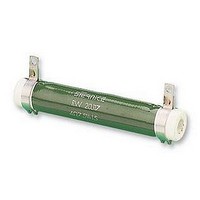
RW20117A470JB15
Manufacturer Part Number
RW20117A470JB15
Description
RESISTORS, WW 72W 5% 47R RESISTORS, WW 72W 5% 47R
Manufacturer
Vishay
Series
RWr
Type
Fixed Wirewound High Power Vitreous Resistors with Terminal Collars or Bandsr
Specifications of RW20117A470JB15
Wirewound Vitreous Enamel
RESISTANCE
Power Rating
72W
Tolerance, +
5%
Tolerance, -
5%
Temp, Op. Max
450(DEGREE C)
Temp, Op. Min
-55(DEGREE C)
Rohs Compliant
YES
Resistance
47 Ohms
Tolerance
5 %
Temperature Coefficient
+ 75 PPM / C
Operating Temperature Range
- 55 C to + 450 C
Dimensions
23 mm Dia. x 117 mm L
Product
Power Resistors Wire Wound Vitreous Enamel
Lead Free Status / Rohs Status
Lead free / RoHS Compliant


MECHANICAL SPECIFICATIONS
Mechanical Protection
Resistive Element
Connections
Average Unit Weight
ENVIRONMENTAL SPECIFICATIONS
Temperature Limits
Climatic Category
NON INDUCTIVE WINDING
For high frequencies, low self induction resistors are available with special windings.
RWNI designation.
Document Number: 50016
Revision: 12-May-09
PERFORMANCE
TESTS
Short Time Overload
Climatic Sequence
Humidity
(Steady State)
Thermal Shock
Shock
Vibration
Terminal Strength
Load Life
SPECIAL FEATURES
RW STYLE
Designation NF C 93-214
Power Rating at 25 °C
Maximum Power
Rating at 25 °C
Ohmic Range
(E12, E24 series)
Limiting Element Voltage
Critical Resistance
MODEL
AND STYLE
Ohmic Range
8 x 34
Fixed Wirewound High Power Vitreous Resistors
RWNI
100 Ω
4.7 Ω
Load at 100 % Pr followed by cold
Enamel
Ni-Cr wire
B band
AN - CR - CS collars
10 g to 100 g
- 55 °C + 450 °C
- 55 °C/+ 200 °C/56 days
1 Ω
Voltage limited at < 5000 V
temp. exposure at - 55 °C
Collar AN Traction 40 N
Band B Torque 60 Ncm
95 % relative humidity
6.9 kΩ
current limited at 5 A
8 x 34
300 V
10 W
13 W
9 shocks/each side
1000 h at Pr 25 °C
- 55 °C + 200 °C
10 Pr during 5 s
-
CONDITIONS
For technical questions, contact:
Severity 55B
90'/30' cycle
Severity 50
with Terminal Collars or Bands
10 kΩ
5 cycles
56 days
10 x 50
RWNI
220 Ω
4.7 Ω
1 Ω
10 x 50
450 V
10 kΩ
17 W
20 W
-
27 kΩ
Insulation resistance > 100 MΩ
Insulation resistance > 100 MΩ
ELECTRICAL SPECIFICATIONS
Resistance Range
Resistance Tolerances
Power Rating
Temperature Coefficient
Dielectric Strength
Insulation Resistance
Shelf Life
sfer@vishay.com
REQUIREMENTS
13 x 70
2.2 Ω
RWNI
620 Ω
4.7 Ω
2 % or 0.05 Ω
3 % or 0.05 Ω
2 % or 0.05 Ω
2 % or 0.05 Ω
1 % or 0.05 Ω
1 % or 0.05 Ω
1 % or 0.05 Ω
RB 13 x 70
13.2 kΩ
13 x 70
650 V
28 W
32 W
5 %
56 kΩ
Standard
2.2 Ω
16 x 94
1.2 kΩ
RWNI
10 Ω
16 x 94
900 V
16 kΩ
44 W
50 W
TYPICAL VALUES AND DRIFTS
-
(E12 peferred series value)
1000 h
5000 h
56 kΩ
1000 V
10 W to 80 W at 25 °C
75 ppm/°C (typical)
0.1 % year (typical)
100 MΩ (500 V
Vishay Sfernice
1 Ω to 68 kΩ
AN collars
RMS
0.25 %
0.25 %
± 5 %
0.5 %
0.5 %
0.5 %
0.5 %
0.5 %
2.7 Ω
(AN collars)
RB 20 x 117
www.vishay.com
20 x 117
20 x 117
2.2 kΩ
15.1 kΩ
RWNI
1100 V
10 Ω
72 W
80 W
DC
1.5 %
2.5 %
)
68 kΩ
RW
59
Related parts for RW20117A470JB15
Image
Part Number
Description
Manufacturer
Datasheet
Request
R

Part Number:
Description:
357-036-542-201 CARDEDGE 36POS DL .156 BLK LOPRO
Manufacturer:
Vishay
Datasheet:
Part Number:
Description:
357-036-542-201 CARDEDGE 36POS DL .156 BLK LOPRO
Manufacturer:
Vishay
Datasheet:
Part Number:
Description:
357-036-542-201 CARDEDGE 36POS DL .156 BLK LOPRO
Manufacturer:
Vishay
Datasheet:
Part Number:
Description:
357-036-542-201 CARDEDGE 36POS DL .156 BLK LOPRO
Manufacturer:
Vishay
Datasheet:
Part Number:
Description:
357-036-542-201 CARDEDGE 36POS DL .156 BLK LOPRO
Manufacturer:
Vishay
Datasheet:
Part Number:
Description:
357-036-542-201 CARDEDGE 36POS DL .156 BLK LOPRO
Manufacturer:
Vishay
Datasheet:
Part Number:
Description:
357-036-542-201 CARDEDGE 36POS DL .156 BLK LOPRO
Manufacturer:
Vishay
Datasheet:
Part Number:
Description:
357-036-542-201 CARDEDGE 36POS DL .156 BLK LOPRO
Manufacturer:
Vishay
Datasheet:
Part Number:
Description:
357-036-542-201 CARDEDGE 36POS DL .156 BLK LOPRO
Manufacturer:
Vishay
Datasheet:
Part Number:
Description:
357-036-542-201 CARDEDGE 36POS DL .156 BLK LOPRO
Manufacturer:
Vishay
Datasheet:
Part Number:
Description:
357-036-542-201 CARDEDGE 36POS DL .156 BLK LOPRO
Manufacturer:
Vishay
Datasheet:
Part Number:
Description:
357-036-542-201 CARDEDGE 36POS DL .156 BLK LOPRO
Manufacturer:
Vishay
Datasheet:
Part Number:
Description:
357-036-542-201 CARDEDGE 36POS DL .156 BLK LOPRO
Manufacturer:
Vishay
Datasheet:
Part Number:
Description:
357-036-542-201 CARDEDGE 36POS DL .156 BLK LOPRO
Manufacturer:
Vishay
Datasheet:
Part Number:
Description:
357-036-542-201 CARDEDGE 36POS DL .156 BLK LOPRO
Manufacturer:
Vishay
Datasheet: