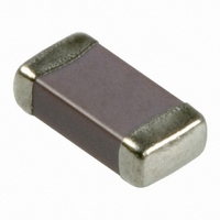
12065G105ZAT2A AVX Corporation, 12065G105ZAT2A Datasheet

12065G105ZAT2A
Specifications of 12065G105ZAT2A
Related parts for 12065G105ZAT2A
12065G105ZAT2A Summary of contents
Page 1
C0G (NP0) Dielectric General Specifications PART NUMBER (see page 2 for complete part number explanation) 0805 A 5 Size Dielectric Capacitance Voltage (L" x W") C0G (NP0 Code (In pF) 6. 10V = Z 2 Sig. ...
Page 2
C0G (NP0) Dielectric Specifications and Test Methods Parameter/Test Operating Temperature Range Capacitance Q Insulation Resistance Dielectric Strength Appearance Capacitance Resistance to Variation Flexure Q Stresses Insulation Resistance ≥ 95% of each terminal should be covered Solderability Appearance No defects, <25% ...
Page 3
C0G (NP0) Dielectric Capacitance Range PREFERRED SIZES ARE SHADED SIZE 0201 0402 Soldering Reflow Only Reflow Only Packaging All Paper All Paper MM 0.60 ± 0.03 1.00 ± 0.10 (L) Length (in.) (0.024 ± 0.001) (0.040 ± 0.004) MM 0.30 ...
Page 4
C0G (NP0) Dielectric Capacitance Range PREFERRED SIZES ARE SHADED SIZE 1210 Soldering Reflow Only Packaging Paper/Embossed MM 3.20 ± 0.20 (L) Length (in.) (0.126 ± 0.008) MM 2.50 ± 0.20 (W) Width (in.) (0.098 ± 0.008) MM 0.50 ± 0.25 ...
Page 5
Packaging of Chip Components Automatic Insertion Packaging TAPE & REEL QUANTITIES All tape and reel specifications are in compliance with RS481. Paper or Embossed Carrier Embossed Only Paper Only Qty. per Reel/7" Reel 2,000, 3,000 or 4,000, 10,000, 15,000 Contact ...
Page 6
Embossed Carrier Configuration 8 & 12mm Tape Only DEFORMATION BETWEEN EMBOSSMENTS A 0 TOP COVER B TAPE CENTER LINES S 1 MAX. CAVITY OF CAVITY SIZE - SEE NOTE 1 ...
Page 7
Paper Carrier Configuration 8 & 12mm Tape Only T BOTTOM TOP COVER COVER TAPE TAPE & 12mm Paper Tape Metric Dimensions Will Govern CONSTANT DIMENSIONS Tape Size +0.10 8mm 1.50 1.75 ± ...
Page 8
Bulk Case Packaging BENEFITS • Easier handling • Smaller packaging volume (1/20 of T/R packaging) • Easier inventory control • Flexibility • Recyclable CASE DIMENSIONS Shutter Slider 12mm 36mm 110mm Attachment Base CASE QUANTITIES Part Size 0402 Qty. 80,000 (pcs ...
Page 9
Basic Capacitor Formulas I. Capacitance (farads) English .224 Metric .0884 II. Energy stored in capacitors (Joules, watt - sec ⁄ III. Linear ...
Page 10
General Description Basic Construction – A multilayer ceramic (MLC) capaci- tor is a monolithic block of ceramic containing two sets of offset, interleaved planar electrodes that extend to two opposite surfaces of the ceramic dielectric. This simple Ceramic Layer Formulations ...
Page 11
General Description Table 1: EIA and MIL Temperature Stable and General Application Codes EIA CODE Percent Capacity Change Over Temperature Range RS198 Temperature Range X7 -55°C to +125°C X6 -55°C to +105°C X5 -55°C to +85°C Y5 -30°C to +85°C ...
Page 12
General Description Typical Cap. Change vs. D.C. Volts X7R 2.5 0 -2.5 -5 -7.5 -10 25% 50% Percent Rated Volts Figure 4 Typical Cap. Change vs. Temperature X7R +20 +10 0VDC 0 -10 -20 -30 -55 -35 -15 +5 +25 ...
Page 13
General Description Effects of Mechanical Stress – High “K” dielectric ceramic capacitors exhibit some low level piezoelectric reactions under mechanical stress general statement, the piezoelectric output is higher, the higher the dielectric constant of the ceramic ...
Page 14
General Description I (Ideal) I (Actual) Loss Phase Angle Angle practice the current leads the voltage by some other phase angle due to the series resistance R ment of this angle is called the loss angle ...
Page 15
Surface Mounting Guide MLC Chip Capacitors REFLOW SOLDERING Case Size D2 0402 0603 0805 D1 D3 1206 1210 D4 1808 1812 1825 D5 2220 2225 Dimensions in millimeters (inches) Component Pad Design Component pads should be designed to achieve good ...
Page 16
Surface Mounting Guide MLC Chip Capacitors APPLICATION NOTES Storage Good solderability is maintained for at least twelve months, provided the components are stored in their “as received” packaging at less than 40°C and 70% RH. Solderability Terminations to be well ...
Page 17
Surface Mounting Guide MLC Chip Capacitors and a target figure 2°C/second is recommended. Although an 80°C to 120°C temperature differential is preferred, recent developments allow a temperature differential between the component surface and the soldering temper- ature of 150°C (Maximum) ...
Page 18
Surface Mounting Guide MLC Chip Capacitors COMMON CAUSES OF MECHANICAL CRACKING The most common source for mechanical stress is board depanelization equipment, such as manual breakapart, v- cutters and shear presses. Improperly aligned or dull cutters may cause torqueing of ...


