2222 139 69478 Vishay, 2222 139 69478 Datasheet - Page 3
2222 139 69478
Manufacturer Part Number
2222 139 69478
Description
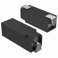
4,7UF 100V 14,3X7,6X8,2 105°C 2000H
Manufacturer
Vishay
Series
139 CLLr
Datasheet
1.2222_139_63101.pdf
(8 pages)
Specifications of 2222 139 69478
Capacitance
4.7µF
Voltage Rating
100V
Tolerance
±20%
Lifetime @ Temp.
2000 Hrs @ 105°C
Operating Temperature
-55°C ~ 105°C
Features
General Purpose
Ripple Current
33mA
Esr (equivalent Series Resistance)
27.00 Ohm
Impedance
11 Ohm
Mounting Type
Surface Mount
Package / Case
Non-Standard SMD
Size / Dimension
0.563" L x 0.299" W (14.30mm x 7.60mm)
Height
0.323" (8.20mm)
Surface Mount Land Size
0.563" L x 0.299" W (14.30mm x 7.60mm)
Lead Free Status / RoHS Status
Lead free / RoHS Compliant
Lead Spacing
-
Lead Free Status / RoHS Status
Lead free / RoHS Compliant
Other names
222213969478
BC1187TR
MAL213969478E3
BC1187TR
MAL213969478E3


Table 2
MOUNTING
The capacitors are designed for automatic placement on to printed-circuit boards or hybrid circuits.
Optimum dimensions of soldering pads depend amongst others on soldering method, mounting accuracy, print lay-out and/or
adjacent components.
For recommended soldering pad dimensions, refer to Fig.3 and Table 2.
SOLDERING
Soldering conditions are defined by the curve, temperature
versus time, where the temperature is that measured on the
soldering pad during processing.
For maximum conditions of different soldering methods see
Figs 4, 5 and 6.
Any temperature versus time curve which does not exceed
the specified maximum curves may be applied.
AS A GENERAL PRINCIPLE, TEMPERATURE AND
DURATION SHALL BE THE MINIMUM NECESSARY
REQUIRED TO ENSURE GOOD SOLDERING
CONNECTIONS. HOWEVER, THE SPECIFIED MAXIMUM
CURVES SHOULD NEVER BE EXCEEDED.
Document Number: 28301
Revision: 28-May-08
RECOMMENDED SOLDERING PAD DIMENSIONS in millimeters (placement accuracy ± 0.25 mm)
NOMINAL CASE SIZE
14.3 x 6.2 x 6.9
14.3 x 7.6 x 8.2
L x W x H
C
reflow soldering
E
B
A
F
15.8
15.8
solder land/
solder paste
pattern
Fig.3 Recommended pad dimensions for reflow and wave soldering
A
For technical questions, contact: aluminumcaps1@vishay.com
8.8
8.8
B
FOR REFLOW SOLDERING
3.5
3.5
C
SMD (Chip) Long Life
Aluminum Capacitors
solder resist
pattern
2.8
2.8
D
D G
8.0
8.0
E
Table 3
16.2
16.2
F
CURING CONDITIONS FOR SMD-GLUE
C
occupied
area
7.7
9.1
G
MAX. T
(°C)
125
140
150
160
160
18.6
18.6
A
amb
wave soldering
10.0
10.0
B
B
A
F
tracks or
dummy tracks
E
FOR WAVE SOLDERING
4.3
4.3
C
MAX. EXPOSURE TIME
5.0
6.0
D
(minutes)
8.8
8.8
E
30
10
5
2
2
139 CLL
www.vishay.com
20.5
21.5
F
Vishay
D G
11.5
13.0
G
3
Related parts for 2222 139 69478
Image
Part Number
Description
Manufacturer
Datasheet
Request
R

Part Number:
Description:
CAP ALUM ELECT 6.3V 100UF SMD
Manufacturer:
Vishay
Datasheet:
Part Number:
Description:
CAP ALUM ELECT 16V 47UF SMD
Manufacturer:
Vishay
Datasheet:
Part Number:
Description:
CAP ALUM ELECT 63V 4.7UF SMD
Manufacturer:
Vishay
Datasheet:
Part Number:
Description:
CAP ALUM ELECT 25V 47UF SMD
Manufacturer:
Vishay
Datasheet:

Part Number:
Description:
CAP ALUM ELECT 40V 33UF SMD
Manufacturer:
Vishay
Datasheet:
Part Number:
Description:
CAP ALUM ELECT 63V 10UF SMD
Manufacturer:
Vishay
Datasheet:
Part Number:
Description:
22UF 50V 14,3X7,6X8,2 105°C 2000H
Manufacturer:
Vishay
Datasheet:
Part Number:
Description:
220UF 6,3V 14,3X7,6X8,2 105°C 2000H
Manufacturer:
Vishay
Datasheet:
Part Number:
Description:
100UF 16V 14,3X7,6X8,2 105°C 2000H
Manufacturer:
Vishay
Datasheet:
Part Number:
Description:
22UF 25V 14,3X6,2X6,9 105°C 2000H
Manufacturer:
Vishay
Datasheet:

Part Number:
Description:
357-036-542-201 CARDEDGE 36POS DL .156 BLK LOPRO
Manufacturer:
Vishay
Datasheet:
Part Number:
Description:
357-036-542-201 CARDEDGE 36POS DL .156 BLK LOPRO
Manufacturer:
Vishay
Datasheet:
Part Number:
Description:
357-036-542-201 CARDEDGE 36POS DL .156 BLK LOPRO
Manufacturer:
Vishay
Datasheet:
Part Number:
Description:
357-036-542-201 CARDEDGE 36POS DL .156 BLK LOPRO
Manufacturer:
Vishay
Datasheet:
Part Number:
Description:
357-036-542-201 CARDEDGE 36POS DL .156 BLK LOPRO
Manufacturer:
Vishay
Datasheet: