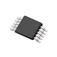
HV831MG Supertex, HV831MG Datasheet - Page 7

HV831MG
Manufacturer Part Number
HV831MG
Description
Display Drivers Hi V Low Noise
Manufacturer
Supertex
Datasheet
1.HV831MG-G.pdf
(8 pages)
Specifications of HV831MG
Driver Type
EL Lamp Drivers
Maximum Operating Temperature
+ 85 C
Mounting Style
SMD/SMT
Package / Case
MSOP-10
Minimum Operating Temperature
- 40 C
Lead Free Status / RoHS Status
Lead free / RoHS Compliant
Available stocks
Company
Part Number
Manufacturer
Quantity
Price
Part Number:
HV831MG
Manufacturer:
SUPERTEX
Quantity:
20 000
Company:
Part Number:
HV831MG-G
Manufacturer:
MAXIM
Quantity:
5
Part Number:
HV831MG-G
Manufacturer:
SUPERTEX
Quantity:
20 000
Pin Configuration and Description
Pin #
10
1
2
3
4
5
6
7
8
9
RSW-Osc
Supertex inc.
Name
COM
GND
VDD
EL2
EL1
CS
C1
C2
LX
Function
Enable input signal for EL lamp 1. Logic high will turn ON the EL lamp 1 and logic low will turn it
OFF. Refer to the Function Table.
Input supply voltage pin.
External resistor connection to set both the switching MOSFET frequency and EL Lamp
frequency. The external resistor should be connected between this pin and the V
lamp frequency is switching frequency divided by 128.
The switching frequency increases as the value of R
provide a switching frequency of 31.2 kHz, and an EL lamp frequency of 244 Hz. To change the
frequency to f
/ f
Enable input signal for EL lamp 2. Logic high will turn ON the EL lamp 2 and logic low will turn it
OFF. Refer to the Function Table.
IC Ground Pin.
External inductor connection to boost the low input voltage using inductive flyback.
Connect an inductor between VIN and this pin. Also connect a high voltage fast recovery
diode between this pin and the CS pin. The anode of the diode needs to be connected
to the LX pin and the cathode to the CS pin. In general, small valued inductors, which can
handle more current, are more suitable for driving large sized lamps. As the inductor
value decreases, the switching frequency should be increased to avoid saturation.
When the switching MOSFET is turned ON, the inductor is being charged. When the MOSFET
is turned OFF, the energy stored in the inductor is transferred to the high voltage capacitor
connected at the CS pin.
Connect a 100V capacitor between this pin and GND. This capacitor stores the energy transferred
from the inductor.
Common connection for both EL lamps. Connect one end of both the lamps to this pin.
EL lamp 2 connection. For optimum performance, the smaller of the two lamps should be
connected to this pin.
EL lamp 1 connection. For optimum performance, the larger of the two lamps should be connected
to this pin.
EL1
MΩ.
●
1235 Bordeaux Drive, Sunnyvale, CA 94089
SW1
, the value of the resistor R
7
SW-OSC1
●
Tel: 408-222-8888
can be determined as R
SW-OSC
decreases. A 470kΩ resistor will
●
www.supertex.com
SW-OSC1
DD
= (470 x 244)
pin. The EL
HV831


