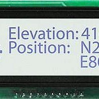
GLK12232-25-SM Matrix Orbital, GLK12232-25-SM Datasheet - Page 8

GLK12232-25-SM
Manufacturer Part Number
GLK12232-25-SM
Description
LCD Graphic Display Modules & Accessories White Background Blue Text
Manufacturer
Matrix Orbital
Datasheet
1.GLK12232-25-SM.pdf
(42 pages)
Specifications of GLK12232-25-SM
Pixel Density
122 x 32
Module Size (w X H X T)
86 mm x 35 mm x 14.4 mm
Viewing Area (w X H)
60.2 mm x 18 mm
Backlighting
White
Background Color
Blue, White
Operating Temperature Range
- 20 C to + 70 C
Attached Touch Screen
No
Product
Graphic LCD Module
Style
LCD Graphic Display
Interface
RS-232, I2C
Lead Free Status / RoHS Status
Lead free / RoHS Compliant
Available stocks
Company
Part Number
Manufacturer
Quantity
Price
Company:
Part Number:
GLK12232-25-SM-R14
Manufacturer:
Matrix Orbital
Quantity:
135
1.8 Trying out a Keypad
unpredictable. At this point all we need to do is make sure that the keypad and interface work, and possibly
generate an ASCII map for any programming needs.
default, a keypress is transmitted as serial data immediately. Keypad buffering can be selected using the
appropriate commands.
1.8.1 Here’s what to do:
To experiment, reverse the connector and see if it generates a more logical set of characters. Ultimately, the
program in the micro-controller will have to ‘map’ these characters to the ones marked on the keypad, which
will likely be different.
1.9 Manual Over-ride
rate which cannot be produced by the host system and all communication to the display is lost, then the user
should follow this simple procedure;
Matrix Orbital
1. The PC should be running a terminal program such as Hyperterm.
2. With the display connected to the PC, plug in the keypad. If the connector has fewer pins than the one
3. Press a key on the keypad. An upper case ASCII character (A-Y) should appear on the PC screen.
1. Turn off the display
2. Put a jumper on pins 5 and 6 of the keypad connector
3. Power up the display. The baud rate is now set to 19,200
4. Remove the jumper and change the RS-232 port settings to the desired baud rate
5. Turn off the display
6. Power up the display
Since a number of different keypad types can be connected to the display, the results may be a little
The keypad interface on the display converts a row / column connection to an ASCII character. By
Manual over-ride should only be required in one instance. If for some reason the module is set at a baud
on the display, center it as well as possible.
Different keys should generate different characters.
NOTES
• The keypad connector must be wired with columns on one side and rows on the other
• The connector is reversible. Reversing the connector will not damage the keypad or
side of the center of the connector. If the keypad isn’t wired this way, an adapter will
need to be made. Another method would be to rewire the connector to meet this
requirement.
the display, but will however, change the ASCII character map.
GLK12232-25-SM
4


