PK202-25 Matrix Orbital, PK202-25 Datasheet - Page 24
PK202-25
Manufacturer Part Number
PK202-25
Description
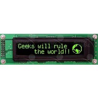
LCD Character Display Modules Black Background Yel/Grn Text
Manufacturer
Matrix Orbital
Series
PK202-25r
Datasheet
1.PK202-25.pdf
(50 pages)
Specifications of PK202-25
Character Count X Line
20 x 2
Module Size (w X H X T)
116 mm x 37 mm x 25.73 mm
Background Color
Black
Backlight Type
LED Yellow / Green
Lead Free Status / RoHS Status
Lead free / RoHS Compliant


4.3 I
first unread key press. A read is initiated by writing to the module with its base address plus 1, then clocking
the module’s return byte after the module releases the SDA line. Much more detail on this basic I
can be found in the I
(every 500 to 1000 ms is typical). All returned key presses indicate the presence or absence of additional
logged key presses by the most significant bit (MSB - bit 7). If the user has pressed two keys since the last
poll of the keypad interface, the first read will return the key code with bit 7 set and the second read will
return the key code with bit 7 clear. The application must take into account this bit to keep up with user key
presses. If there are no keypresses detected, the module will return zero (0x00).
4.4 RS-232 Interface
rate. This behavior can be modified using commands found in the next section.
Matrix Orbital
The keypad can be read by I
A good reference is also available at:
The module contains a ten key press buffer so that it can be polled for key presses at an infrequent rate
By default on any press of a key, the module will immediately send out the key code at the selected baud
NOTE The keypads may be laid out in a different pattern. If this is the case, the user
will need to interpret the key codes differently. Also included are two extra pins on each
end of the connector to be used for ground strapping. This can be used in conjunction with
your keypad if a ground strap connection is required or if a common ground connection is
needed.
NOTE The keypad connector must be wired with columns on one side and rows on the
other side of the center of the connector. In situations where the keypad isn’t wired this
way an adapter will need to be made, or the user should rewire the connector to meet this
requirement.
2
C Interface
2
C specification by Phillips.
2
C master read. This means that a read of the module will always return the
Rows
Table 9: Keypad Layout
1
2
3
4
5
PK202-25
A
K
U
F
P
1
Columns
B
G
Q
V
L
2
W
M
H
C
R
3
D
N
X
4
S
I
O
Y
E
T
5
J
2
C function
20
Related parts for PK202-25
Image
Part Number
Description
Manufacturer
Datasheet
Request
R

Part Number:
Description:
LCD Character Display Modules Black Background Yel/Grn Text
Manufacturer:
Matrix Orbital

Part Number:
Description:
DISPLAY
Manufacturer:
Matrix Orbital
Datasheet:
Part Number:
Description:
LCD ACCY VFD FILTER 20X2 BLUE
Manufacturer:
Matrix Orbital
Datasheet:
Part Number:
Description:
LCD ACCY VFD FILTER 20X2 RED
Manufacturer:
Matrix Orbital
Datasheet:
Part Number:
Description:
LCD ACCY VFD FILTER 20X2 GREEN
Manufacturer:
Matrix Orbital
Datasheet:
Part Number:
Description:
LCD ACCY VFD FILTER 20X4 BLUE
Manufacturer:
Matrix Orbital
Datasheet:
Part Number:
Description:
LCD ACCY VFD FILTER 20X4 RED
Manufacturer:
Matrix Orbital
Datasheet:
Part Number:
Description:
LCD ACCY VFD FILTER 20X4 GREEN
Manufacturer:
Matrix Orbital
Datasheet:

Part Number:
Description:
DISPLAY
Manufacturer:
Matrix Orbital
Datasheet:

Part Number:
Description:
VFD DISPLAY 16X2 SER/I2C
Manufacturer:
Matrix Orbital
Datasheet:

Part Number:
Description:
VFD ALPHA/NUM DISPL 20X2 SER/I2C
Manufacturer:
Matrix Orbital
Datasheet:

Part Number:
Description:
VFD ALPHA/NUM DISPL 16X2 SER/I2C
Manufacturer:
Matrix Orbital
Datasheet:
Part Number:
Description:
VFD ALPHA/NUM DISPL 20X2 SER/I2C
Manufacturer:
Matrix Orbital
Datasheet: