HFBR-57M5AP Avago Technologies US Inc., HFBR-57M5AP Datasheet - Page 8
HFBR-57M5AP
Manufacturer Part Number
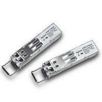
HFBR-57M5AP
Description
Fiber Optic Transmitters, Receivers, Transceivers 2/1 GBd FC SFP DMI B ail delatch
Manufacturer
Avago Technologies US Inc.
Datasheet
1.HFBR-57M5AP.pdf
(18 pages)
Specifications of HFBR-57M5AP
Function
Supports high-speed serial links over multimode optical fiber at signaling rates up to 2.125 GBd.
Product
Transceiver
Data Rate
2.125 GBd, 1.0625 GBd, 1.25 GBd
Wavelength
850 nm
Maximum Rise Time
250 ps, 150 ps
Maximum Fall Time
250 ps, 150 ps
Pulse Width Distortion
0.12 ns, 0.123 ns
Operating Supply Voltage
2.97 V to 3.63 V
Maximum Operating Temperature
+ 75 C
Minimum Operating Temperature
- 10 C
Package / Case
SFP-20
Optical Fiber Type
TX/RX
Data Transfer Rate
2125Mbps
Optical Rise Time
0.15/0.25ns
Optical Fall Time
0.15/0.25ns
Jitter
0.12/0.123ns
Operating Temperature Classification
Commercial
Peak Wavelength
860nm
Package Type
SFP
Operating Supply Voltage (min)
2.97V
Operating Supply Voltage (typ)
3.3V
Operating Supply Voltage (max)
3.63V
Operating Temp Range
-10C to 75C
Mounting
Snap Fit To Panel
Pin Count
20
For Use With
Multimode Glass
Lead Free Status / RoHS Status
Lead free / RoHS Compliant


Transmitter Optical Characteristics
TC = -10 °C to +85 °C, V
8
Notes:
1. Max Pout is the lesser of Class 1 safety limits (CDRH and EN 60825) or receiver power, max.
2. Into 62.5/125 µm (0.275 NA) and 50/125 µm (0.2 NA) multimode optical fiber.
3. An OMA of 196 µw is approximately equal to an average power of –9 dBm assuming an Extinction Ratio of 9 dB.
4. An OMA of 156 µw is approximately equal to an average power of –10 dBm assuming an Extinction Ratio of 9 dB.
5. Contributed DJ is measured on an oscilloscope in average mode with 50% threshold and K28.5 pattern.
6. Contributed RJ is calculated for 1x10
Parameter
Modulated Optical Output Power (OMA, pk-pk)
2.125 Gb/s
Modulated Optical Output Power (OMA, pk-pk)
1.0625 Gb/s
Average Optical Output Power
Optical Extinction Ratio
Center Wavelength
Spectral Width - rms
Optical Rise/Fall Time
2.125 Gb/s
Optical Rise/Fall Time
1.0625 Gb/s
RIN
Contributed Deterministic Jitter (Transmitter)
2.125 Gb/s
Contributed Deterministic Jitter (Transmitter)
1.0625 Gb/s
Contributed Total Jitter (Transmitter)
2.125 Gb/s
Contributed Total Jitter (Transmitter)
1.0625 Gb/s
P
OUT
14. Per FC-PI (Table 13 - MM jitter output, note 1), the actual contributed RJ is allowed to increase above its limit if the actual contributed DJ
decreases below its limits, as long as the component output DJ and TJ remain within their specified FC-PI maximum limits with the worst case
specified component jitter input.
12
TX_DISABLE Asserted
(OMA)
CC
T, V
CC
R = 3.3 V ± 10%
-12
BER by multiplying the RMS jitter (measured on a single rise or fall edge) from the oscilloscope by
Symbol
OMA
OMA
P
ER
l
s, rms
tr, tf
tr, tf
RIN
DJ
DJ
TJ
TJ
P
C
OUT
OFF
Minimum
196
156
-9.5
9
830
Typical
Maximum
860
0.85
150
300
-117
0.12
56
0.09
85
0.25
120
0.27
252
-35
Unit
µW
µW
dBm
dB
nm
nm
ps
ps
dB/Hz
UI
ps
UI
ps
UI
ps
UI
ps
dBm
Notes
3
4
1, 2
20-80%
20-80%
5
5
6
6
Related parts for HFBR-57M5AP
Image
Part Number
Description
Manufacturer
Datasheet
Request
R

Part Number:
Description:
XMITTER OPTICAL 2MBD SERCOS
Manufacturer:
Avago Technologies US Inc.
Datasheet:
Part Number:
Description:
Fiber Optic Transmitters, Receivers, Transceivers SERCOS TRANSMITTER
Manufacturer:
Avago Technologies US Inc.

Part Number:
Description:
RECEIVER FIBER OPTIC 600NM 40KBD
Manufacturer:
Avago Technologies US Inc.
Datasheet:

Part Number:
Description:
XMITTER FIBER OPTIC 600NM 5MBD
Manufacturer:
Avago Technologies US Inc.
Datasheet:

Part Number:
Description:
XMITTER FIBER OPTIC 600NM 40KBD
Manufacturer:
Avago Technologies US Inc.
Datasheet:

Part Number:
Description:
XMITTER VERSATILE LINK HORZ
Manufacturer:
Avago Technologies US Inc.
Datasheet:

Part Number:
Description:
XMITTER OPT HI PERFORMANCE VERT
Manufacturer:
Avago Technologies US Inc.
Datasheet:

Part Number:
Description:
TXRX FIBER OPTIC 650NM 10MBAUD
Manufacturer:
Avago Technologies US Inc.
Datasheet:
Part Number:
Description:
TXRX FIBER OPTIC 650NM 10MBAUD
Manufacturer:
Avago Technologies US Inc.
Datasheet:

Part Number:
Description:
FIBER OPTIC TRANSMITTER 660NM
Manufacturer:
Avago Technologies US Inc.
Datasheet:

Part Number:
Description:
KIT EVAL FIBER OPTIC 5MBD
Manufacturer:
Avago Technologies US Inc.
Datasheet:
Part Number:
Description:
KIT EVAL FIBER OPTICS 32MBD
Manufacturer:
Avago Technologies US Inc.
Datasheet:

Part Number:
Description:
KIT EVAL FIBER OPTIC 5MBD
Manufacturer:
Avago Technologies US Inc.
Datasheet:

Part Number:
Description:
125MBd 1300nm FiberOptic Eval Kit
Manufacturer:
Avago Technologies US Inc.
Datasheet:

Part Number:
Description:
DC-5MBd 820nm FiberOptic EvalKit
Manufacturer:
Avago Technologies US Inc.
Datasheet: