GP1UE26RK0VF Sharp Microelectronics, GP1UE26RK0VF Datasheet

Infrared Receivers Rem Cont Receiver 3V 40 kHz

GP1UE26RK0VF

Manufacturer Part Number
GP1UE26RK0VF
Description
Infrared Receivers Rem Cont Receiver 3V 40 kHz
Manufacturer
Sharp Microelectronics
Datasheet

Specifications of GP1UE26RK0VF

Carrier Frequency
40 KHz
High Level Pulse Width
1200 us
Low Level Pulse Width
1000 us
Minimum High Level Output Voltage
2.2 V
Operating Voltage
2.7 V to 5.5 V
Supply Current
0.27 mA
Maximum Operating Temperature
+ 70 C
Minimum Operating Temperature
- 10 C
Sensing Distance
10m
B.p.f. Center Frequency
40.0kHz
Voltage - Supply
2.7 V ~ 5.5 V
Current - Supply
400µA
Orientation
Top View
Mounting Type
Through Hole
Lead Free Status / RoHS Status
Lead free / RoHS Compliant
■ Features
GP1UE26RK0VF/GP1UE27RK0VF Series
GP1UE28RK0VF/GP1UE28QK0VF Series
1.
2.
3. Anti electomagnetic induction noise type.
4. Compact (case volume).
5.
6. Lead-free and RoHS directive compliant.
■ Outline Dimens ions
Notice The content of data sheet is subject to change without prior notice.
Low operating voltage:2.7 to 5.5V
Low dissipation current:MAX. 0.4mA(at Vcc=3V)
Various B.P.F. (Band-Pass Filter) frequency to meetdifferent user needs.
GP1UE26RK0VF Series
1.*1 : Indicates root dimensions of connector.
2.Unspecified tolerance : ±0.3
3.Case thickness : 0.3TYP
4.*2 : Exclude sagged solder
5.*3 : If there are difficulties to insert the
*1
0.7
In the absence of confirmation by device specification sheets, SHARP takes no responsibility for any defects that may occur in equipment using any SHARP
devices shown in catalogs, data books, etc. Contact SHARP in order to obtain the latest device specification sheets before using any SHARP device.
2.54
0.5
*1
we recommend to expand 0.1mm from original 2.9mm.
2.54
1
5.6
2
3
0.7
1
2
3
V
V
G ND
OUT
C C
Example of mounting drawing
from solder side (Reference)
2.2
*3
2.54
2.9
1.4
GP1UE26RK0VF
3
5
8.6
*3
5.8
2
0.5
3.6
1
C enter
of P D
2.54
*3
1.4
2.9
series on PCB,
*1
3.6
0.5
1.*1 : Indicates root dimensions of connector.
2.Unspecified tolerance : ±0.3
3.Case thickness : 0.3TYP
4.*2 : Exclude sagged solder
5.*3 : If there are difficulties to insert the
GP1UE27RK0VF Series
1
1.25
*1
0.8
2.54
0.5
we recommend to expand 0.1mm from original 2.9mm.
*1
2.54
Low Voltage Operation,Anti Electromagnetic
induction Noise Type,Compact IR Detecting Unit
for Remote Control
1
5.6
2
■ Applications
3
1. AV equipments
2. Home appliances
GP1UE26RK0VF/GP1UE27RK0VF Series
GP1UE28RK0VF/GP1UE28QK0VF Series
1.25
0.8
1
2
3
V
V
G ND
OUT
C C
2.2
Example of mounting drawing
from solder side (Reference)
GP1UE27RK0VF
10.2
13.8
*3
2.54
2.9
1.4
0.5
3
*3
5.8
3.6
2
C enter
1
series on PCB,
of P D
2.54
Sheet No.: OP06006
*3
1.4
(Unit : mm)
2.9
*2
3.6
0.5

Related parts for GP1UE26RK0VF

GP1UE26RK0VF Summary of contents

Page 1

... In the absence of confirmation by device specification sheets, SHARP takes no responsibility for any defects that may occur in equipment using any SHARP devices shown in catalogs, data books, etc. Contact SHARP in order to obtain the latest device specification sheets before using any SHARP device. GP1UE26RK0VF/GP1UE27RK0VF Series GP1UE28RK0VF/GP1UE28QK0VF Series ...

Page 2

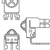
... PD 4.*2 : Exclude sagged solder 5.* there are difficulties to insert the recommend to expand 0.1mm from original 2.9mm. 2.54 series on PCB, Model No. GP1UE27RK0VF GP1UE270RKVF GP1UE271RKVF GP1UE272RKVF GP1UE273RKVF 2 GP1UE26RK0VF/GP1UE27RK0VF Series GP1UE28RK0VF/GP1UE28QK0VF Series (Unit : mm) 2.2 2.75 0.4 *1 1.7 0.8 3.7 1 OUT 2.54 5 ...

Page 3

... Parameter Rating Unit V Supply voltage 0 to +6.0 ℃ ℃ 265 ℃ Symbol Conditions I No input light =1.6mA GP1UE26RK0VF/GP1UE27RK0VF Series GP1UE28RK0VF/GP1UE28QK0VF Series OUT V CC GND Symbol Operating conditions Unit V 2 =25℃, V =3V MIN. TYP. MAX. Unit 0. 0.45 V 1200 μ ...

Page 4

... In the above figure, the transmitter should be set so that the output V However, the PD49PI to be used here should be of the short-circuit current illuminance by CIE standard light source A (tungsten lamp).) V Fig.2 Standard Optical System Transmitter GP1UE26RK0VF/GP1UE27RK0VF Series GP1UE28RK0VF/GP1UE28QK0VF Series 20cm 10kΩ Oscilloscope ...

Page 5

... N V 2 200μs or more ON t 400μs or more OFF Transmitting time for 1 block /T) ×100 (%) Σ N=1 GND (Circuit parameters and GND to improve anti-static electricity proof GP1UE26RK0VF/GP1UE27RK0VF Series GP1UE28RK0VF/GP1UE28QK0VF Series 3.0 to 5.5V 300μs or more 47Ω±5% 47μ Sheet No.: OP06006 ...

Page 6

... Depend on the flux you select, there are different solderabilities, so please select a suitable flux and use it. 13. This product dose`t correspond to soldering by reflow. 14. Please use this device away from the dew drop. Be aware that the dew drop rusts shield case and others, may affect the electric characteristics. GP1UE26RK0VF/GP1UE27RK0VF Series GP1UE28RK0VF/GP1UE28QK0VF Series 6 Sheet No.: OP06006 ...

Related keywords