HSDL-3209-021 Lite-On Electronics, HSDL-3209-021 Datasheet - Page 12
HSDL-3209-021
Manufacturer Part Number
HSDL-3209-021
Description
Infrared Transceivers IR Transceiver 115Kb/s
Manufacturer
Lite-On Electronics
Datasheet
1.HSDL-3209-021.pdf
(16 pages)
Specifications of HSDL-3209-021
Wavelength
875 nm, 880 nm
Continual Data Transmission
115.2 Kbit/s
Radiant Intensity
14 mW/sr
Half Intensity Angle Degrees
30 deg to 60 deg
Pulse Width
4 ms, 1.6 ms
Maximum Rise Time
60 ns, 600 ns
Maximum Fall Time
60 ns, 600 ns
Led Supply Voltage
0 V to 6.5 V
Maximum Forward Current
50 mA
Operating Voltage
2.4 V to 3.6 V
Maximum Operating Temperature
+ 70 C
Minimum Operating Temperature
- 25 C
Dimensions
7 mm x 2.8 mm x 1.6 mm
Data Rate
115.2kbs (SIR)
Idle Current, Typ @ 25° C
100µA
Link Range, Low Power
30cm
Operating Temperature
-25°C ~ 70°C
Orientation
Side View
Shutdown
*
Size
7mm x 2.8mm x 1.6mm
Standards
IrPHY 1.4
Supply Voltage
2.4 V ~ 3.6 V
Lead Free Status / RoHS Status
Lead free / RoHS Compliant
Available stocks
Company
Part Number
Manufacturer
Quantity
Price
Company:

Part Number:
HSDL-3209-021
Manufacturer:
AVAGO
Quantity:
2 385


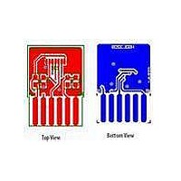
Appendix B: PCB Layout Suggestion
The HSDL 3209 is a shieldless part and hence does not
contain a shield trace unlike the other transceivers. The
following PCB layout guidelines should be followed to
obtain a good PSRR and EM immunity resulting in good
electrical performance. Things to note:
1. The ground plane should be continuous under the
2. VLED can be connected to either unfiltered or unreg-
The area underneath the module at the second layer, and
3cm in all direction around the module is defined as the
critical ground plane zone. The ground plane should be
maximized in this zone. Refer to application note AN1114
or the Lite-On Technology IrDA Data Link Design Guide
for details. The layout below is based on a 2-layer PCB.
1
part.
ulated power supply. If VLED and Vcc share the same
power supply, CX3 need not be used and the connec-
tions for CX1 and CX2 should be before the current
limiting resistor R1. CX1 is generally a ceramic capaci-
Top layer
Connect the metal shield & module
ground pin to bottom ground layer
Layer 2
Critical ground plane zone. Do not connect
directly to the module ground pin
Layer 3
Keep data bus away from critical ground
plane zone
Bottom layer
(GND)
3. Preferably a multi-layered board should be used to
tor of low inductance providing a wide frequency
response while CX2 and CX3 are tantalum capacitors
of big volume and fast frequency response. The use
of a tantalum capacitor is more critical on the VLED
line, which carries a high current. CX4 is an optional
ceramic capacitor, similar to CX1, for the IOVcc line.
provide sufficient ground plane. Use the layer un-
derneath and near the transceiver module as Vcc,
and sandwich that layer between ground connected
board layers. Refer to the diagram below for an ex-
ample of a 4 layer board,
Top View
Bottom View
Related parts for HSDL-3209-021
Image
Part Number
Description
Manufacturer
Datasheet
Request
R

Part Number:
Description:
EMITTER IR 5MM 875NM
Manufacturer:
Lite-On Electronics
Datasheet:

Part Number:
Description:
ENCODER/DECODER 3/16 8-SOIC
Manufacturer:
Lite-On Electronics
Datasheet:

Part Number:
Description:
PHOTOSENSOR MINI 3V 550NM 6-PLCC
Manufacturer:
Avago Technologies US Inc.

Part Number:
Description:
Infrared Transceiver
Manufacturer:
Avago Technologies US Inc.

Part Number:
Description:
Infrared Transceivers IR Transceiver 115.2Kb/s
Manufacturer:
Lite-On Electronics
Datasheet:

Part Number:
Description:
Infrared Transceivers FIR + RC
Manufacturer:
Avago Technologies US Inc.
Datasheet:

Part Number:
Description:
Manufacturer:
Avago Technologies
Datasheet:

Part Number:
Description:
Manufacturer:
Agilent Technologies, Inc.
Datasheet:
Part Number:
Description:
EMITTER IR FLAT 875NM SHORT LDS
Manufacturer:
Lite-On Electronics
Datasheet:
Part Number:
Description:
EMITTER IR FLAT 875NM LONG LDS
Manufacturer:
Lite-On Electronics
Datasheet:
Part Number:
Description:
Standard LED - SMD Polyled Emmiter Long Leads
Manufacturer:
Lite-On Electronics
Datasheet:

Part Number:
Description:
IC ENCODER/DECODER IRDA 16-SOIC
Manufacturer:
Lite-On Electronics
Datasheet:

Part Number:
Description:
IC ENCODER/DECODER IRDA 16-QFN
Manufacturer:
Lite-On Electronics
Datasheet:
Part Number:
Description:
ENCODER/DECODER 3/16 8-SOIC
Manufacturer:
Lite-On Electronics
Datasheet:
Part Number:
Description:
ENCODER/DECODER 3/16 CLK 16-SOIC
Manufacturer:
Lite-On Electronics
Datasheet: