CM252016-220KL Bourns Inc., CM252016-220KL Datasheet - Page 2
CM252016-220KL
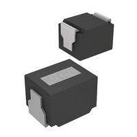
Manufacturer Part Number
CM252016-220KL
Description
Inductor,Ferrite,22uH,10+% Tol,10-% Tol,1008-Case
Manufacturer
Bourns Inc.
Series
CM252016r
Specifications of CM252016-220KL
Inductance
22µH
Current
60mA
Tolerance
±10%
Dc Resistance (dcr)
5.800 Ohm Max
Q @ Freq
25 @ 2.52MHz
Self Resonant Freq
22MHz
Package / Case
0.098" L x 0.079" W x 0.063" H (2.50mm x 2.00mm x 1.60mm)
Mounting Type
Surface Mount
Operating Temperature
-40°C ~ 100°C
Frequency - Test
2.52MHz
Material - Core
Ferrite
Applications
Mobile Communications
Termination Style
SMD/SMT
Lead Free Status / RoHS Status
Lead free / RoHS Compliant
Shielding
-
Current - Saturation
-
Current - Temperature Rise
-
Lead Free Status / Rohs Status
Lead free / RoHS Compliant


CM10, CM16, CM20, CM25, CM32
Specifications are subject to change without notice.
Model
CM10
CM16
CM20
CM25
CM32
CM45
Packaging Specifications
Reel Dimensions
Soldering
Flow Soldering
Packaging
t1
Model
CM10
CM16
CM20
Flow Soldering
CM10
CM16
CM20
CM25
CM32
CM45
Model
Vapor-phase
t2
Infra-red
CM45, CM32, CM25, CM20, CM16, CM10 SMT Chip Inductors
Preheat:
100 to 150°
2 minutes
min.
0.71 (.027) 1.21 (.047) 8.00 (.315) 3.50 (.138) 1.75 (.069) 4.00 (.157) 2.00 (.079) 4.00 (.157) 1.50 (.059) 0.60 (.024) 0.27 (.011)
1.00 (.039) 1.80 (.071) 8.00(.315)
1.45 (.057) 2.25 (.089) 8.00(.315)
2.40 (.094) 2.90 (.114) 8.00(.315)
2.80 (.110) 3.60 (.142) 8.00(.315)
3.60 (.142) 4.90 (.193) 12.00(.472) 5.50 (.217) 1.75 (.069) 8.00 (.315) 2.00 (.079) 4.00 (.157) 1.50 (.059)
A
W
178 (7.008)
178 (7.008)
178 (7.008)
178 (7.008)
178 (7.008)
178 (7.008)
Chip
Component
10000 pcs
E
Quantity
3000 pcs
3000 pcs
10 seconds max.
F
A
260°C maximum for 5 seconds (2 wave solder method)
200°C for a maximum of 30 seconds. Peak of 240°C for a maximum of 5 seconds.
If the solder does not reflow simultaneously under each terminal, there may be a misalignment of the component on the
board. For this reason, it is recommended that the inductor be adhered to the board prior to reflow.
215°C for a maximum of 30 seconds.
B
260°C
60 min. 13 (.512) 21 (.827)
60 min. 13 (.512) 21 (.827)
60 min. 13 (.512) 21 (.827)
60 min. 13 (.512) 21 (.827)
60 min. 13 (.512) 21 (.827)
60 min. 13 (.512) 21 (.827)
flDo
DIA.
B
D1
P1
Weight
150g
90g
90g
W
P2
Tape running direction
C
P3
3.50 (.138) 1.75 (.069) 4.00 (.157) 2.00 (.079) 4.00 (.157) 1.50 (.059) 0.60 (.024) 0.27 (.011)
3.50 (.138) 1.75 (.069) 4.00 (.157) 2.00 (.079) 4.00 (.157) 1.50 (.059) 1.00 (.039) 0.25 (.010)
3.50 (.138) 1.75 (.069) 4.00 (.157) 2.00 (.079) 4.00 (.157) 1.50 (.059) 1.10 (.043) 0.25 (.010)
3.50 (.138) 1.75 (.069) 4.00 (.157) 2.00 (.079) 4.00 (.157) 1.50 (.059)
F
A
Infra-red Soldering
D
Model
CM25
CM32
CM45
E
Preheat:
100 to 150°
2 minutes
min.
2 (.079)
2 (.079)
2 (.079)
2 (.079)
2 (.079)
2 (.079) 13 (.512)
B
E
Quantity
2000 pcs
2000 pcs
500 pcs
10 seconds max.
30 seconds max.
P1
9 (.354)
9 (.354)
9 (.354)
9 (.354)
9 (.354)
W
CM45
230°C
t1
200°C
t2
P2
Weight
100g
190g
100g
Chip
Component
W
E
P3
F
øD0
Vapor-phase Soldering
flDo
P1
A
Preheat:
100 to 150°
2 minutes
min.
P2
øD1
Tape running direction
—
—
10 seconds max.
30 seconds max.
P3
E
0.25 (.010)
0.30 (.012)
220°C
C
t1
A
D
215°C
1.20 (.047)
1.20 (.047)
1.55 (.061)
1.85 (.073)
2.40 (.094)
3.50 (.138)
B
t2
W
B
Related parts for CM252016-220KL
Image
Part Number
Description
Manufacturer
Datasheet
Request
R

Part Number:
Description:
Manufacturer:
Bourns, Inc.
Datasheet:

Part Number:
Description:
INDUCTOR CHIP 2.7UH 2520 SMD
Manufacturer:
Bourns Inc.
Datasheet:
Part Number:
Description:
INDUCTOR CHIP .012UH 2520 SMD
Manufacturer:
Bourns Inc.
Datasheet:
Part Number:
Description:
INDUCTOR CHIP .22UH 2520 SMD
Manufacturer:
Bourns Inc.
Datasheet:
Part Number:
Description:
INDUCTOR CHIP .33UH 2520 SMD
Manufacturer:
Bourns Inc.
Datasheet:
Part Number:
Description:
INDUCTOR CHIP .39UH 2520 SMD
Manufacturer:
Bourns Inc.
Datasheet:
Part Number:
Description:
INDUCTOR CHIP .47UH 2520 SMD
Manufacturer:
Bourns Inc.
Datasheet:
Part Number:
Description:
INDUCTOR CHIP .56UH 2520 SMD
Manufacturer:
Bourns Inc.
Datasheet:
Part Number:
Description:
INDUCTOR CHIP .68UH 2520 SMD
Manufacturer:
Bourns Inc.
Datasheet:
Part Number:
Description:
INDUCTOR CHIP .82UH 2520 SMD
Manufacturer:
Bourns Inc.
Datasheet:
Part Number:
Description:
Manufacturer:
Bourns, Inc.
Datasheet:
Part Number:
Description:
11mm Potentiometer
Manufacturer:
Bourns, Inc.
Datasheet: