D-436-43 Tyco Electronics, D-436-43 Datasheet

CONN SPLICE BUTT 18-22AWG YLW

D-436-43

Manufacturer Part Number
D-436-43
Description
CONN SPLICE BUTT 18-22AWG YLW
Manufacturer
Tyco Electronics
Series
D-436r
Datasheet

Specifications of D-436-43

Terminal Type
Butt Splice, Inline, Individual Openings
Number Of Wire Entries
Varies by Wire Size
Termination
Crimp
Wire Gauge
18-22 AWG
Insulation
Fully Insulated
Features
Heat Shrink
Color
Blue, Yellow Stripe
Connector Type
Butt Splice
Insulator Color
Yellow
Termination Method
Crimp
Wire Size (awg)
22-18
Contact Material
Copper
Contact Plating
Tin
Insulator Material
PVDF
Chemical Resistant
No
Lead Free Status / RoHS Status
Lead free / RoHS Compliant
Lead Free Status / RoHS Status
Lead free / RoHS Compliant, Lead free / RoHS Compliant
Other names
5-1195131-6
650073-000
MATERIALS
1. INSULATION SLEEVE: Heat-shrinkable, transparent blue, radiation cross-linked modified polyvinylidene
2. INTEGRAL MULTI-WIRE SEAL: Modified thermoplastic.
3. SEPARATE MULTI-WIRE SEAL: Modified thermoplastic.
4. CRIMP SPLICER: Base Metal: Copper Alloy 101 or 102 per ASTM B-75.
D-436-42
D-436-43
APPLICATION
1. These parts are designed to provide an immersion resistant in-line splices of 2 or 3 to 2 or 3 wires falling within
2. Parts are available only as an assembly of one of each Item #1 and Item #2.
3. Crimp splicer may be installed with Raychem AD-1377 crimp tool or equivalent.
4. Inside diameter and outside diameter of splice are to be measured in crimp area, 2.54 to 5.08 (0.100 to 0.200)
5. Acceptance sampling shall be in accordance with paragraph 4.6.1 of MIL-T-7928.
6 . Packing and packaging shall be in accordance with Section 5, Level C, of MIL-T-7928.
7. This document takes precedence over documents referenced herein.
UNLESS OTHERWISE SPECIFIED DIMENSIONS ARE IN MILLIMETERS.
INCHES DIMENSIONS ARE BETWEEN BRACKETS.
TOLERANCES:
0.00 N/A
0.0 N/A
0 N/A
DRAWN BY:
If this document is printed it becomes uncontrolled. Check for the latest revision.
flouride.
Name
from ends of part. Slight burr permitted on parted surfaces.
the size range listed above, having insulations rated for at least 135 C.
M. FORONDA
Part
Prod.
Rev.
ANGLES: N/A
ROUGHNESS IN
MICRON
A
F
Plating: Tin per MIL-T-10727, Type 1.
Color Code: See table below.
(I.D.±0.002)
1.70 (0.067)
2.54 (0.100)
I.D.±0.05
REPLACES:
Dimensions: Crimp Splice
Menlo Park, CA 94025, USA
Tyco Electronics reserves the right to amend this
drawing at any time. Users should evaluate the
suitability of the product for their application.
Tyco Electronics Corporation
N/A
305 Constitution Drive
SPECIFICATION CONTROL DRAWING
(O.D.±0.003)
2.62 (0.103)
3.81 (0.150)
O.D.±0.08
DCR NUMBER:
D001303
Yellow
Color
Code
Blue
Raychem
Products
Installation Data: Wire Size Range of Crimp Splicer
Minimum
2 x 24
2 x 22
DOCUMENT NO.:
DATE:
PROD. REV.
SEE TABLE
Two Wires
05-Dec.-00
Maximum
TITLE :
D-436-42/-43
2 x 20
2 x 16
IN-LINE SPLICE SEALING
SCALE:
SYSTEM, MULTI-WIRE
None
SIZE:
Minimum
3 x 24
3 x 22
A
Three Wires
DOC ISSUE:
1
SHEET:
Maximum
1 of 4
3 x 22
3 x 18

Related parts for D-436-43

D-436-43 Summary of contents

Page 1

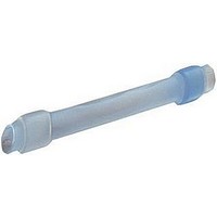
... Name Rev. (I.D.±0.002) D-436-42 F 1.70 (0.067) D-436-43 A 2.54 (0.100) APPLICATION 1. These parts are designed to provide an immersion resistant in-line splices wires falling within the size range listed above, having insulations rated for at least 135 C. 2. Parts are available only as an assembly of one of each Item #1 and Item #2. ...

Page 2

... MIL-W-81044/12 or MIL-W-16878/4. The assemblies shall be divided equally between the maximum and minimum wire size as shown below: Assembly Minimum D-436-42 D-436-43 The qualification sample shall consists of 35 assemblies and 8 uninstalled sleeves. 1.1 Acceptance Testing: Acceptance sampling shall be in accordance with ANSI/ASQC Z1.4, Inspection Level S-4. The Acceptable Quality Level shall be 4 ...

Page 3

... Altitude Immersion Insulation Resistance Voltage Drop** Tensile Strength * Test methods are per MIL-STD-202. ** Test current shall be equal to 3X the rated current fot the smallest gauge wire used. 2.4 Test Group C: Ten Assemblies: Test Sequence Insulation Resistance Salt Spray (Corrosion)*** Insulation Resistance ...

Page 4

... Position the separate seal as close as possible to the splicer. Hold this piece in position by squeezing the wires directly behind it, and slide the sealing sleeve over the assembly so that the separate seal is as far inside the sleeve as possible. d) Apply heat, using the recommended heat source, first to the “separate” seal end, and then the other. ...

Related keywords