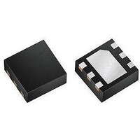
MAX9635EDT+T Maxim Integrated Products, MAX9635EDT+T Datasheet - Page 9

MAX9635EDT+T
Manufacturer Part Number
MAX9635EDT+T
Description
Optical Sensors - Board Mount Low-Power Ambient Li ght Sensor with ADC
Manufacturer
Maxim Integrated Products
Datasheet
1.MAX9635EDTT.pdf
(20 pages)
Specifications of MAX9635EDT+T
Supply Current
0.65 uA
Operating Supply Voltage
1.7 V to 3.6 V
Maximum Power Dissipation
953 mW
Package / Case
uTDFN-6
Maximum Operating Temperature
+ 85 C
Minimum Operating Temperature
- 40 C
Lead Free Status / RoHS Status
Lead free / RoHS Compliant
The TIM[2:0] bits can be used to program the signal integration time.
In automatic mode (MANUAL = 0), integration time is automatically selected by the on-chip algorithm to be either
100ms/200ms/400ms/800ms. In manual mode (MANUAL = 1), integration time can be varied by the user all the way
from 6.25ms to 800ms. See Table 7.
Table 7. Integration Time
Bits in Lux High-Byte register 0x03 give the 4 bits of exponent E3:E0 and 4 most significant bits of the mantissa byte
M7:M4, and represent the lux reading of ambient light. The remaining 4 bits of the mantissa byte M3:M0 are in the Lux
Low-Byte register 0x04 and enhance resolution of the lux reading from the IC.
Exponent (E[3:0]): Exponent bits of the lux reading (0000 to 1110). Note: A reading of 1111 represents an overrange
condition.
Mantissa (M[7:4]): Four most significant bits of mantissa byte of the lux reading (0000 to 1111).
Lux = 2
Exponent = 8xE3 + 4xE2 + 2xE1 + E0
Mantissa = 8xM7 + 4xM6 + 2xM5 + M4
A code of 0000 0001 calculates to be 0.72 lux.
A code of 1110 1111 calculates to be 176,947 lux.
A code of 1110 1110 calculates to be 165,151 lux.
Update of the contents of this register is internally disabled during I
between internal ADC and I
If user wants to read both the Lux High-Byte register 0x03 and Lux Low-Byte register 0x04, then the master should
not send a STOP command between the reads of the two registers. Instead a REPEATED START command should
be used. This ensures accurate data is obtained from the I
process).
TIM[2:0]
BIT 7
000
001
010
011
100
101
110
111
E3
(exponent)
x mantissa x 0.72
BIT 6
INTEGRATION
E2
TIME (ms)
12.5
6.25
800
400
200
100
50
25
2
C registers. Update of I
BIT 5
E1
This is a preferred mode for boosting low-light sensitivity.
—
—
This is a preferred mode for high-brightness applications.
Manual mode only.
Manual mode only.
Manual mode only.
Manual mode only.
Ambient Light Sensor with ADC
BIT 4
E0
2
C registers is resumed when the master sends a STOP command.
BIT 3
Industry’s Lowest-Power
M7
2
C registers (by disabling internal updates during the read
2
C read operations to ensure proper data transfer
BIT 2
COMMENTS
M6
Lux High-Byte Register 0x03
BIT 1
M5
Integration Timer Bits (TIM[2:0])
BIT 0
M4
REGISTER
ADDRESS
0x03
9


