E3G-R17 Omron, E3G-R17 Datasheet - Page 8
E3G-R17
Manufacturer Part Number
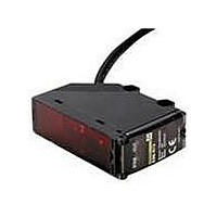
E3G-R17
Description
Photoelectric Sensors - Industrial Retro 10M DC Connector
Manufacturer
Omron
Series
E3Gr
Datasheet
1.E3G-L73.pdf
(13 pages)
Specifications of E3G-R17
Output Current
100mA
Sensor Output
NPN/PNP
Supply Voltage Range Dc
10V To 30V
Mounting Type
Bracket
Switch Terminals
Cable
Sensor Housing
Rectangular
Sensor Input
Optical
Output Type
Transistor
Sensing Distance
393.701" (10m)
Sensing Method
Retroreflective
Sensing Object
Mirror
Output Configuration
NPN/PNP - Dark-ON/Light-ON - Selectable
Sensing Light
Red
Current - Supply
50mA
Voltage - Supply
10 V ~ 30 V
Package / Case
Module, Connector
Features
Compact Model
Lead Free Status / RoHS Status
Lead free / RoHS Compliant
Lead Free Status / RoHS Status
Lead free / RoHS Compliant, Lead free / RoHS Compliant


Safety Precautions
Refer to Warranty and Limitations of Liability.
This product is not designed or rated for ensuring
safety of persons either directly or indirectly.
Do not use it for such purposes.
Do not use the product in atmospheres or environments that exceed
product ratings.
● Designing
Power Supply
A power supply with full-wave rectification can be connected to the
E3G-MR19(T).
● Wiring
The tensile strength of the cable during operation should not exceed
the values shown below.
● Adjusting
Indicators
● Designing
Power Supply
A power supply with full-wave rectification can be connected to the
E3G-ML79(T).
● Wiring
The tensile strength of the cable during operation should not exceed
the values shown below.
E3G-R13
E3G-MR19(T)
E3G-R17
• The following illustration indicates the operating levels of the E3G.
• Set the E3G so that it will work within the stable operation range.
E3G-L73
E3G-ML79(T)
E3G-L77
*If the operating level is set to the stable operation range, the E3G will operate with the
highest reliability and without being influenced by temperature change, voltage fluctuation,
dust, or setting change. If the operating level cannot be set to the stable operation range,
pay close attention to environmental changes while operating the E3G.
Stable
operation
range*
Unstable
operation
range *
Stable
operation
range*
Model
Model
E3G-R/MR
E3G-L/ML
Operating
level x 1.2
Operating
level
Operating
level x 0.8
Precautions for Correct Use
Stability indicator
Tensile strength
Tensile strength
(green)
OFF
ON
ON
50 N max.
10 N max.
50 N max.
10 N max.
WARNING
(torque)
(torque)
Operation indicator (orange)
L. ON
OFF
ON
D. ON
OFF
ON
● Mounting
Mounting
Mounting Directions
Install the Sensor as shown in the following if each sensing object
greatly differs in color or material.
● Others
EEPROM Write Errors
If a teaching data error occurs with the operation indicator flashing
due to a power failure or static noise, perform the teaching operation
of the Sensor again.
• Make sure that the sensing side of the
If the sensing object has a glossy
surface, incline the Sensor by 5° to 10°
as shown below, provided that the
Sensor is not influenced by any
background objects.
• If there is a mirror-like object below the Sensor, the Sensor may not
• Make sure not to install the Sensor in the incorrect direction. Refer
Sensor is parallel with the surface of
each sensing object. Do not incline the
Sensor towards the sensing object.
be in stable operation. Therefore, incline the Sensor or keep the
Sensor a distance away from the mirror-like object as shown below.
to the following.
Sensing
object
Moving direction
Sensing
object
Moving direction
Moving direction
Sensing
object
Mirror-like object
Moving direction
Sensing
object
Moving direction
Glossy object
Surface of
sensing object
Sensing side
E3G
8
Related parts for E3G-R17
Image
Part Number
Description
Manufacturer
Datasheet
Request
R

Part Number:
Description:
CONVERGENT 50mm PNP CONN.
Manufacturer:
Omron
Datasheet:
Part Number:
Description:
Photoelectric Sensors - Industrial CONVERGENT 200MM PNP CONN
Manufacturer:
Omron
Datasheet:

Part Number:
Description:
Photoelectric Sensors - Industrial NPN/PNP POL RETRORFL
Manufacturer:
Omron
Datasheet:
Part Number:
Description:
Photoelectric Sensors - Industrial CONVERGENT 2M DC CONN.
Manufacturer:
Omron
Datasheet:
Part Number:
Description:
Photoelectric Sensors - Industrial RETRO 10M AC/DC TMR. SCREW TERM
Manufacturer:
Omron
Datasheet:

Part Number:
Description:
Photoelectric Sensors - Industrial CONVERGENT 2M AC/DC SCREW TERM
Manufacturer:
Omron
Datasheet:
Part Number:
Description:
Photoelectric Sensors - Industrial RETRO 10M AC/DC SCRE W TERM.
Manufacturer:
Omron
Datasheet:
Part Number:
Description:
Photoelectric Sensors - Industrial Retro 10M DC E39-R2 not incl.
Manufacturer:
Omron
Datasheet:
Part Number:
Description:
Photoelectric Sensors - Industrial CONVERGENT 200mm NPN CONN.
Manufacturer:
Omron
Datasheet:
Part Number:
Description:
Photoelectric Sensors - Industrial NPN/PNP DIFF REFLECT
Manufacturer:
Omron
Datasheet:

Part Number:
Description:
G6S-2GLow Signal Relay
Manufacturer:
Omron Corporation
Datasheet:
Part Number:
Description:
Compact, Low-cost, SSR Switching 5 to 20 A
Manufacturer:
Omron Corporation
Datasheet:
Part Number:
Description:
Manufacturer:
Omron Corporation
Datasheet: