E3S-LS10XE4 Omron, E3S-LS10XE4 Datasheet - Page 17
E3S-LS10XE4
Manufacturer Part Number
E3S-LS10XE4
Description
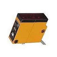
Photoelectric Sensors - Industrial PROXIMITY
Manufacturer
Omron
Type
Background Supression Sensorr
Series
E3S-LSr
Specifications of E3S-LS10XE4
Features
Pin point focusable and area focusable models eliminate back ground objects
Sensing Method
Diffuse Reflective
Sensing Distance
10 cm
Light Source
Red LED
Amplifier Type
Built In DC Amplifiers
Connection
Prewired Cable
Output Configuration
NPN
Sensing Range
3cm To 10cm
Output Current
80mA
Sensor Output
NPN
Supply Voltage Range Dc
12V To 24V
Length/height, External
55mm
Response Time
1ms
Output Type
Transistor
Sensor Input
Optical
Sensing Object
White Paper
Sensing Light
Red
Mounting Type
Bracket Mount
Current - Supply
40mA
Voltage - Supply
12 V ~ 24 V
Package / Case
Module, Pre-Wired
Lead Free Status / RoHS Status
Lead free / RoHS Compliant
Lead Free Status / RoHS Status
Lead free / RoHS Compliant, Lead free / RoHS Compliant
Available stocks
Company
Part Number
Manufacturer
Quantity
Price
Company:

Part Number:
E3S-LS10XE4
Manufacturer:
OMRON
Quantity:
475


E39-S46 Slit Set
Using slits allows smaller objects to be detected and reduces
the sensing distance.
Use the rubber attachment with the metal cover if a slit width of
2 mm is required. Insert the 0.5- or 1-mm slit between the metal
cover and rubber attachment if a slit width of 0.5 or 1 mm is
desired. These slits fit into the rubber attachment.
NOTE: Apply the slit to the lens of the photoelectric sensor
Use this attachment when the set distance is long and
adjustment is mechanically difficult with a sensing object.
Attach the reflector to the receiver (refer to the figure).
Look at the reflector from right behind the emitter. The
reflector should be bright with red light when the optical
beam strikes the reflector. If the emitter has a turbo
function, the reflector looks brighter with the function
switched on.
When the reflector is removed, the light beam strikes the
receiver.
Adjuster Cap (Supplied with each sensor)
In order to prevent the sensitivity or OFF-delay time that
has been set from changing accidentally, cover the
adjusters with the adjuster cap (enclosed).
A set of 4 filters are sold together for two through-beam
models (for 2 each of emitters and receivers).
The arrow printed on the cover indicates the direction of
polarization. By attaching the filters opposite to each other
in polarization to the emitters and the receivers (refer to
the figure) in rows, mutual interference can be prevented
(in any case, the filter attached to an emitter and to the
corresponding receiver must be the same in direction of
polarization or the photoelectric sensor will not function).
E3S-A
Slit width Sensing distance
0.5 mm
1 mm
2 mm
SLITS FOR THROUGH-BEAM SENSORS
OPTICAL AXIS CONFIRMATION REFLECTOR E39-R5
ADJUSTER CAP AND OPTIONAL E39-G2 SENSITIVITY ADJUSTER KNOB
E39-E6 MUTUAL INTERFERENCE FILTER
marked with an arrow indicating the position of the
optical axis (apply it to the bottom lens of horizontal
sensors and the top lens of vertical sensors).
0.5 m (1.64 ft)
1.1 m (3.61 ft)
2.4 m (8.20 ft)
Aduster cap
Aduster
Min. object size
0.5 mm (0.02 in)
Press the adjuster cap until
this face touches the name
plate on the sensor.
1 mm (0.04 in)
2 mm (0.08 in)
18
E39-G2 Adjuster Knob
To temporarily use the knob to adjust the sensitivity of the
photoelectric sensor, insert side A into the shaft of the
sensitivity adjuster. To snap the adjuster onto the sensor,
push side B onto the sensitivity knob.
Notches to hold cover
Eye
Receiver
2 mm
Metal cover
E3S-A
Emitter
Slit (0.5 mm or 1 mm)
Emitter
Rubber attachment
(A)
(B)
E39-R5
Be aware of the direction of
polarization.
Optical axis
confirmation
reflector
Arrow indicating
position
of optical axis
Receiver
E3S-A
Related parts for E3S-LS10XE4
Image
Part Number
Description
Manufacturer
Datasheet
Request
R

Part Number:
Description:
Photoelectric Sensors - Industrial Background suppress diff. refl. 5-25cm
Manufacturer:
Omron
Datasheet:
Part Number:
Description:
Photoelectric Sensors - Industrial Photoelectric Sensor
Manufacturer:
Omron
Datasheet:
Part Number:
Description:
Photoelectric Sensors - Industrial Photoelectric Sensor
Manufacturer:
Omron
Datasheet:
Part Number:
Description:
Photoelectric Sensors - Industrial PCB REFLECTIVE 30mm
Manufacturer:
Omron
Datasheet:

Part Number:
Description:
Photoelectric Sensors - Industrial SPEC.3 PIN CONNECTOR MODEL
Manufacturer:
Omron
Datasheet:
Part Number:
Description:
PCB WIDE BEAM SENSOR LONG DIST
Manufacturer:
Omron
Datasheet:
Part Number:
Description:
DEF. DISTANCE
Manufacturer:
Omron
Datasheet:
Part Number:
Description:
EMITTER ONLY FOR E3S-AT16
Manufacturer:
Omron
Datasheet:
Part Number:
Description:
DETECTOR ONLY FOR E3S-BT31
Manufacturer:
Omron
Datasheet:
Part Number:
Description:
RECEIVER ONLY FOR E3S-AT16
Manufacturer:
Omron
Datasheet:

Part Number:
Description:
G6S-2GLow Signal Relay
Manufacturer:
Omron Corporation
Datasheet:
Part Number:
Description:
Compact, Low-cost, SSR Switching 5 to 20 A
Manufacturer:
Omron Corporation
Datasheet:
Part Number:
Description:
Manufacturer:
Omron Corporation
Datasheet: