TSL201R TAOS, TSL201R Datasheet - Page 4
TSL201R
Manufacturer Part Number
TSL201R
Description
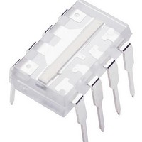
Photodiodes Linear Sensor Array 200dpi 64pix
Manufacturer
TAOS
Type
Linear Sensor Arrayr
Datasheet
1.TSL201R.pdf
(10 pages)
Specifications of TSL201R
Peak Wavelength
1000 nm
Package / Case
PDIP-8
Maximum Operating Temperature
+ 70 C
Minimum Operating Temperature
0 C
Mounting Style
Through Hole
Lead Free Status / RoHS Status
Lead free / RoHS Compliant
Available stocks
Company
Part Number
Manufacturer
Quantity
Price
Company:

Part Number:
TSL201R
Manufacturer:
PHILIPS
Quantity:
420
Part Number:
TSL201R
Manufacturer:
TAOS
Quantity:
20 000
Part Number:
TSL201R-LF
Manufacturer:
TAOS
Quantity:
20 000


TSL201R−LF
64 y 1 LINEAR SENSOR ARRAY
TAOS077B − MAY 2007
Electrical Characteristics at f
R
NOTES: 1. The array is uniformly illuminated with a diffused LED source having a peak wavelength of 640 nm.
Timing Requirements (see Figure 1 and Figure 2)
NOTES: 9. Input pulses have the following characteristics: t
Dynamic Characteristics over recommended ranges of supply voltage and operating free-air
temperature (see Figure 2)
4
Copyright E 2007, TAOS Inc.
V
V
PRNU
R
SE
V
DSNU
IL
I
I
I
C
C
t
t
t
t
t
DD
IH
IL
su(SI)
h(SI)
w
r
s
L
, t
out
drk
sat
e
i(SI)
i(CLK)
f
= 330 Ω, E
10. SI must go low before the rising edge of the next clock pulse.
Analog output settling time to ± 1%
Setup time, serial input (see Note 9)
Hold time, serial input (see Note 9 and Note 10)
Pulse duration, clock high or low
Input transition (rise and fall) time
Analog output voltage (white, average over 64 pixels) see Note 1
Analog output voltage (dark, average over 64 pixels)
Pixel response nonuniformity
Nonlinearity of analog output voltage
Output noise voltage
Responsivity (See Note 5)
Saturation exposure
Analog output saturation voltage
Dark signal nonuniformity
Image lag
Supply current, output idle
High-level input current
Low-level input current
Input capacitance, SI
Input capacitance, CLK
2. PRNU is the maximum difference between the voltage from any single pixel and the average output voltage from all pixels of the
3. Nonlinearity is defined as the maximum deviation from a best-fit straight line over the dark-to-white irradiance levels, as a percent
4. RMS noise is the standard deviation of a single-pixel output under constant illumination as observed over a 5-second period.
5. R
6. Minimum saturation exposure is calculated using the minimum V
7. DSNU is the difference between the maximum and minimum output voltage in the absence of illumination.
8. Image lag is a residual signal left in a pixel from a previous exposure. It is defined as a percent of white-level signal remaining after
device under test when the array is uniformly illuminated at the white irradiance level. PRNU includes DSNU.
of analog output voltage (white).
a pixel is exposed to a white condition followed by a dark condition:
e(min)
e
= 16.5 μW/cm
= [V
PARAMETER
out(min)
PARAMETER
− V
drk(max)
2
clock
(unless otherwise noted)
]
÷
(E
e
= 1 MHz, V
×
r
t
int
IL +
)
www.taosinc.com
V out (white) * V drk
V out (IL) * V drk
r
= 6 ns, t
DD
E
See Notes 2 & 3
See Note 3
See Note 4
See Note 6
All pixels, E
See Note 8
V
V
e
I
I
= V
= 0
= 0
= 5 V, T
f
DD
TEST CONDITIONS
= 6 ns.
e
R
sat
= 0
L
A
TEST CONDITIONS
, the maximum V
= 330 Ω,
= 25°C, λ
100
See Note 7
C
L
r
= 10 pF
p
drk
= 640 nm, t
, and the maximum R
MIN
MIN
1.6
2.5
18
20
50
0
0
0
The LUMENOLOGY r Company
MIN
± 0.4%
0.5%
NOM
± 4%
TYP
int
142
3.4
3.4
50
23
25
TYP
2
1
5
5
185
= 5 ms,
± 7.5%
e
.
MAX
MAX
MAX
120
120
500
2.4
5
1
1
(μJ/cm
mVrms
nJ/cm
UNIT
UNIT
UNIT
mV
mV
mA
FS
μA
μA
pF
pF
V/
ns
ns
ns
ns
V
V
ns
2
2
)
Related parts for TSL201R
Image
Part Number
Description
Manufacturer
Datasheet
Request
R

Part Number:
Description:
Microcontroller Modules & Accessories TAOS Eval Module w/USB Interface
Manufacturer:
TAOS
Part Number:
Description:
Optical Sensor Development Tools TAOS Eval Module
Manufacturer:
TAOS

Part Number:
Description:
Industrial Optical Sensors Ambient Light Sensor SMBus
Manufacturer:
TAOS
Datasheet:

Part Number:
Description:
Photodiodes TriColor Sensor RGB, Clear Ch
Manufacturer:
TAOS
Datasheet:

Part Number:
Description:
LED Displays Hexadecimal Display 4-bit
Manufacturer:
TAOS
Datasheet:

Part Number:
Description:
Industrial Optical Sensors Ambient Light Sensor SMBus
Manufacturer:
TAOS
Datasheet:

Part Number:
Description:
Photodiodes Linear Array 200 DPI
Manufacturer:
TAOS
Datasheet:

Part Number:
Description:
Photodiodes Light to Voltage Converter
Manufacturer:
TAOS
Datasheet:

Part Number:
Description:
Photodiodes Linear Array 200 DPI
Manufacturer:
TAOS
Datasheet:

Part Number:
Description:
Photodiodes Light to Voltage Converter
Manufacturer:
TAOS
Datasheet:
Part Number:
Description:
Industrial Optical Sensors Ambient Light Sensor SMBus
Manufacturer:
TAOS
Datasheet:
Part Number:
Description:
Photodiodes TriColor Sensor RGB, Clear Ch
Manufacturer:
TAOS
Datasheet:
Part Number:
Description:
LED Displays Hexadecimal Display 4-bit
Manufacturer:
TAOS
Datasheet:
