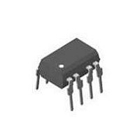
SFH6741 Vishay, SFH6741 Datasheet

SFH6741
Specifications of SFH6741
Related parts for SFH6741
SFH6741 Summary of contents
Page 1
... Ground loop elimination Description The 6N137, SFH674x and SFH675x are single chan- nel 10 Mbd optocouplers utilizing a high efficient input LED coupled with an integrated optical photodiode IC detector. The detector has an open drain NMOS-tran- Document Number 82584 Rev. 1.8, 13-Aug-04 6N137/ SFH6741 / Single channel ...
Page 2
... SFH6741 / Vishay Semiconductors Part Remarks SFH6751-X006 5 kV/µs, Dual channel, DIP-8 400 mil (option 6) SFH6751-X007 5 kV/µs, Dual channel, SMD-8 (option 7) SFH6752 10 kV/µs, Dual channel, DIP-8 SFH6752-X006 10 kV/µs, Dual channel, DIP-8 400 mil (option 6) SFH6752-X007 10 kV/µs, Dual channel, SMD-8 (option 7) ...
Page 3
... I (sinking Input threshold current I (sinking High level enable current Low level enable current High level enable voltage Low level enable voltage Document Number 82584 Rev. 1.8, 13-Aug-04 6N137/ SFH6741 / Test condition Symbol T amb Test condition Symbol Symbol I ...
Page 4
... SFH6741 / Vishay Semiconductors Switching Characteristics Over Recommended Temperature ( 100 °C All Typicals ° Parameter = 350 Ω, C Propagation delay time to high R L output level = 350 Ω, C Propagation delay time to low R L output level = 350 Ω, C Pulse width distortion 350 Ω, C Propagation delay skew ...
Page 5
... Pulse Gen Ω Monitoring Node Single Channel 7 OUT GND The Probe and Jig Capacitances are included in C Document Number 82584 Rev. 1.8, 13-Aug-04 6N137/ SFH6741 / Output Monitoring Node 0.1 µF 6 Bypass PLH Output V O Input V E 0.1 µF Monitoring Bypass Node Output Figure 3 ...
Page 6
... SFH6741 / Vishay Semiconductors Common Mode Transient Immunity Parameter Test condition Common mode | transient immunity = 350 Ω O(min) L (high 350 Ω O(min kV 350 Ω O(min 0 O(max 0 O(max kV 0 O(max) 1) For 6N137 and SFH6750 2) For SFH6741 and SFH6751 3) For SFH6742 and SFH6752 ...
Page 7
... F 1.5 1 1.1 1.0 –40 – – Ambient Temperature ( ° 17610 amb Figure 6. Forward Voltage vs. Ambient Temperature Document Number 82584 Rev. 1.8, 13-Aug-04 6N137/ SFH6741 / Dual Channel 0.1 µ Bypass 4 5 GND Pulse Generator Ω O Test condition Symbol CTI standard DIP-8 ...
Page 8
... SFH6741 / Vishay Semiconductors –40 – – Ambient Temperature ( C ) 17613-1 amb Figure 8. Reverse Current vs. Ambient Temperature 4.0 3 2.0 1.5 1.0 0.5 0.0 –40 – – Ambient Temperature ( C ) 17614 amb Figure 9. Low Level Supply Current vs. Ambient Temperature 3.2 ...
Page 9
... 0 – Forward Input Current ( mA ) 17621 F Figure 16. Output Voltage vs. Forward Input Current Document Number 82584 Rev. 1.8, 13-Aug-04 6N137/ SFH6741 / 120 100 100 –40 –20 17622 Figure 17. Propagation Delay vs. Ambient Temperature 120 100 100 17623 Figure 18. Propagation Delay vs. Forward Current ...
Page 10
... SFH6741 / Vishay Semiconductors 350 Ω – Forward Current ( mA ) 17625 F Figure 20. Pulse Width Distortion vs. Forward Current 300 kΩ 250 200 150 = 350 Ω kΩ 100 kΩ kΩ 350 Ω –40 – – Ambient Temperature ( ° 17626 amb Figure 21. Rise and Fall Time vs. Ambient Temperature ...
Page 11
... MIN. .014 (0.35) .010 (0.25) .400 (10.16) .430 (10.92) Document Number 82584 Rev. 1.8, 13-Aug-04 6N137/ SFH6741 / pin one ISO Method A .300 (7.62) .031 (0.79) typ. .130 (3.30) .150 (3.81) 10° .020 (.51 ) 3° ...
Page 12
... SFH6741 / Vishay Semiconductors Ozone Depleting Substances Policy Statement It is the policy of Vishay Semiconductor GmbH to 1. Meet all present and future national and international statutory requirements. 2. Regularly and continuously improve the performance of our products, processes, distribution and operatingsystems with respect to their impact on the health and safety of our employees and the public, as well as their impact on the environment ...
Page 13
... Document Number 82584 Rev. 1.8, 13-Aug-04 6N137/ SFH6741 / Vishay Semiconductors www.vishay.com 13 ...
Page 14
This datasheet has been download from: www.datasheetcatalog.com Datasheets for electronics components. ...


