MVK25VC331M10X10TP United Chemi-Con, MVK25VC331M10X10TP Datasheet - Page 2
MVK25VC331M10X10TP
Manufacturer Part Number
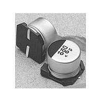
MVK25VC331M10X10TP
Description
CAPACITOR ALUM ELEC, 330UF, 25V
Manufacturer
United Chemi-Con
Type
Electrolyticr
Datasheet
1.MVK25VC331M10X10TP.pdf
(5 pages)
Specifications of MVK25VC331M10X10TP
Tolerance (+ Or -)
20%
Voltage
25VDC
Esr
804mOhm
Mounting Style
Surface Mount
Construction
Cylindrical
Dcl
3uA
Lifetime
2000
Product Diameter (mm)
10mm
Product Height (mm)
10mm
Product Depth (mm)
Not Requiredmm
Product Length (mm)
Not Requiredmm
Seated Plane Height
Not Requiredmm
Lead Spacing (nom)
Not Requiredmm
Lead Diameter (nom)
Not Requiredmm
Operating Temp Range
-40C to 125C
Capacitance
330uF
Ripple Current
450mA
Capacitance Tolerance
± 20%
Voltage Rating
25V
Termination Type
SMD
Working Voltage, Dc
25V
Ripple Current Ac
450mA
Operating Temperature Max
105°C
Rohs Compliant
No
Lead Free Status / RoHS Status
Compliant


MVK Series
MVK Specifications
Part Numbering System for MVK Series
Operating Temperature Range
Rated Voltage Range
Capacitance Range
Capacitance Tolerance
Leakage Current
Dissipation Factor ( Tan )
Low Temperature
Characteristics
Load Life
Shelf Life
Others
MVK
United Chemi-Con, Inc. 9801 W. Higgins Road, Rosemont, IL 60018 Tel 847-696-2000 Fax 847-696-9278 www.chemi-con.com
10
Item
VC
101
M
6.3 to 50VDC
0.1 to 1,000 F
I
Where I = Leakage current ( A ), C = Nominal capacitance ( F ) and V = Rated voltage ( V )
At
At 120Hz, impedance ( Z ) ratio between the
exceed the values given below.
The following specifications shall be satisfied when the capacitors are restored to
subjecting them to the DC rated voltage for the specified test time at 105 C. The sum of DC
voltage and peak AC voltage must not exceed the full rated voltage of the capacitors.
Size
Capacitance change:
Tan
Leakage current
The following specifications shall be satisfied when the capacitors are restored to
after exposing them for the specified test time at 105 C without voltage applied. The rated
voltage shall be applied to the capacitors for a minimum of 30 minutes, at least 24 hours and
not more than 48 hours before the measurements.
Size
Capacitance change:
Tan
Leakage current
Satisfies characteristic W of JIS C5141
8X6
Rated Voltage ( V )
Size
Size
Rated Voltage ( V )
Z ( 25 C ) / Z ( 20 C )
Z ( 40 C ) / Z ( 20 C )
40 to 105 C
20% ( M ) at
Size
Size
Size
Size
Size
Size
0.01CV or 3 A, whichever is greater, after 2 minutes at
20 C, 120Hz
Ø
Ø
Ø
Ø
( DF ):
( DF ):
4-
4-
4-
8 &
Ø
Ø
Ø
Ø
Ø
Ø
Ø
Ø
Ø
4-
8 &
4-
8 &
4-
8 &
TP
6.3: 1,000 hours
6.3: 500 hours
6.3
Ø
10
Ø
Ø
Ø
Ø
Ø
Ø
6.3
6.3
6.3
10
10
10
20 C, 120Hz
When ordering, always specify complete catalog number for MVK Series.
: ≤
: ≤
: ≤ 300% of the initial specified value
: ≤ 200% of the initial specified value
: ≤ initial specified value
: ≤
: ≤
: ≤ 200% of the initial specified value
: ≤ initial specified value
Lead Length: TP is for Standard Taping.
Case Code: See Case Sizes in Tables.
Capacitance Tolerance: M =
Capacitance Value: Expressed in Microfarads. The first two digits are
significant figures, and the third digit indicates the number of zeros
for capacitance of 100 F or more. R indicates the decimal point for
capacitance less than 100 F (e.g. R10 = .10 F; 1R0 = 1.0 F;
10R = 10 F; 101 = 100 F; 102 = 1,000 F; 103 = 10,000 F ).
Lead Configuration: VC = Vertical Chip Lead Terminals.
DC Rated Voltage: Expressed in Volts (e.g. 10 = 10WVDC).
Series Name: Indicates Basic Capacitor Design.
30% of the initial measured value
20% of the initial measured value
25% of the initial measured value
20% of the initial measured value
0.30
0.40
10
6.3
6.3
4
Size
Size
Ø
8 &
Ø
0.24
0.30
8 &
Characteristics
10
10
3
8
Ø
10: 1,000 hours
Ø
10: 2,000 hours
25 C or
0.20
0.26
16
16
2
6
20%
40 C value and
20 C.
0.16
0.16
25
25
2
4
20 C value shall not
0.14
0.14
35
35
2
3
20 C after
20 C
0.12
0.12
50
50
2
3
45
Related parts for MVK25VC331M10X10TP
Image
Part Number
Description
Manufacturer
Datasheet
Request
R

Part Number:
Description:
CAP 82UF 16V ELECT POLY SMD
Manufacturer:
United Chemi-Con
Datasheet:

Part Number:
Description:
CAP 220UF 100V ELECT KZE RAD
Manufacturer:
United Chemi-Con
Datasheet:

Part Number:
Description:
CAP 82UF 450V ELECT KXG RAD
Manufacturer:
United Chemi-Con
Datasheet:

Part Number:
Description:
CAP 100UF 6.3V ELECT MZA SMD
Manufacturer:
United Chemi-Con
Datasheet:

Part Number:
Description:
CAP 330UF 16V ELECT POLY SMD
Manufacturer:
United Chemi-Con
Datasheet:
Part Number:
Description:
CAP 1200UF 4.0V ELECT POLY SMD
Manufacturer:
United Chemi-Con
Datasheet:
Part Number:
Description:
CAP 560UF 10V ELECT POLY SMD
Manufacturer:
United Chemi-Con
Datasheet:

Part Number:
Description:
CAP 1000UF 35V ELECT LXY RAD
Manufacturer:
United Chemi-Con
Datasheet:

Part Number:
Description:
CAP CER 15UF 50V X7R 2220
Manufacturer:
United Chemi-Con
Datasheet:
Part Number:
Description:
Multilayer Ceramic Capacitors (MLCC) - SMD/SMT 22UF 50V -20+80%
Manufacturer:
United Chemi-Con
Datasheet:
Part Number:
Description:
BULK / CAP 270UF 10V ELECT POLY RAD
Manufacturer:
United Chemi-Con
Part Number:
Description:
Capacitor,10uF,50VDC,20-% Tol,20+% Tol
Manufacturer:
United Chemi-Con
Part Number:
Description:
Bulk / Capacitor, Aluminum, 450 V, Cap.150 , Dia.18 , Leng.45
Manufacturer:
United Chemi-Con

Part Number:
Description:
Multilayer Ceramic Capacitors (MLCC) - SMD/SMT 22UF 25V -20+80%
Manufacturer:
United Chemi-Con
Datasheet:

Part Number:
Description:
CAP DOUBLE LAYER 350F 2.5V SCREW
Manufacturer:
United Chemi-Con
Datasheet: