228112315101 Vishay, 228112315101 Datasheet - Page 7
228112315101
Manufacturer Part Number
228112315101
Description
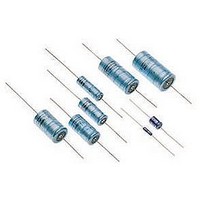
CAPACITOR ALUM ELECT 100UF, 16V, AXIAL
Manufacturer
Vishay
Type
Electrolyticr
Series
123 SAL-Ar
Datasheet
1.228112315101.pdf
(12 pages)
Specifications of 228112315101
Esr
2.8Ohm
Capacitance
100uF
Tolerance (+ Or -)
20%
Voltage
16VDC
Mounting Style
Through Hole
Construction
Axial
Dcl
160uA
Lifetime
20000
Product Diameter (mm)
9.4mm
Product Height (mm)
Not Requiredmm
Product Depth (mm)
Not Requiredmm
Product Length (mm)
23.3mm
Seated Plane Height
Not Requiredmm
Lead Spacing (nom)
Not Requiredmm
Lead Diameter (nom)
0.6mm
Operating Temp Range
-55C to 125C
Ripple Current
260mA
Capacitor Dielectric Type
Aluminium Electrolytic
Capacitance Tolerance
± 20%
Life Time @ Temperature
5000 Hours @ 125°C
Voltage Rating
16VDC
Lead Free Status / RoHS Status
Compliant


IMPEDANCE (Z)
Document Number: 28355
Revision: 23-Jun-08
( )
( )
( )
Ω
Ω
Z
Ω
Z
Z
10
10
10
10
10
10
10
10
10
10
10
10
1
1
1
3
2
-1
3
2
-1
2
-1
-2
10
10
10
Case Ø D x L = 6.7 x 20.4 mm
U
Fig.10 Typical impedance as a function of frequency
Fig.14 Typical impedance as a function of frequency
Case Ø D x L = 9.4 x 23.3 mm; U
Case Ø D x L = 6.7 x 15.3 mm; U
R
Fig.12 Typical impedance as a function of frequency
= 6.3 to 16 V
1
2
3
4
5
6
10
1
2
3
4
5
10
10
1
2
3
2
2
2
10
10
10
3
3
3
10
10
10
4
4
R
Curve 1: 33 µF, 16 V
Curve 2: 47 µF, 16 V
Curve 3: 68 µF, 10 V
Curve 4: 100 µF, 6.3 and 10 V
Curve 5: 150 µF, 6.3 V
4
R
Curve 1: 10 µF, 16 V
Curve 2: 15 µF, 16 V
Curve 3: 22 µF, 16 V
Curve 4: 33 µF, 10 V
Curve 5: 47 µF, 6.3 and 10 V
Curve 6: 68 µF, 6.3 V
= 6.3 to 10 V
= 6.3 to 16 V
Curve 1: 150V, 10 V
Curve 2: 220 V, 10V
Curve 3: 330 V, 6.3 V
For technical questions, contact: aluminumcaps2@vishay.com
10
10
10
5
5
5
Aluminum Capacitors
T
T
T
10
10
10
amb
amb
amb
6
6
6
= 25 °C
= 25 °C
= 25 °C
f (Hz)
f (Hz)
f (Hz)
Solid Axial
10
10
10
7
7
7
( )
( )
( )
Ω
Ω
Ω
Z
Z
Z
10
10
10
10
10
10
10
10
10
10
1
10
10
1
1
3
2
-1
3
2
-1
4
3
2
10
10
10
Fig.13 Typical impedance as a function of frequency
Fig.15 Typical impedance as a function of frequency
Fig.11 Typical impedance as a function of frequency
Case Ø D x L = 6.7 x 15.3 mm;
U
Case Ø D x L = 9.4 x 23.3 mm;
U
Case Ø D x L = 6.7 x 20.4 mm; U
R
R
= 25 to 40 V
= 16 to 40 V
1
2
3
4
5
6
1
2
3
4
5
6
10
10
1
2
3
4
5
6
10
2
2
2
10
10
10
Vishay BCcomponents
3
3
3
10
10
10
4
R
4
4
Curve 1: 2.2 µF, 35 and 40 V
Curve 2: 3.3 µF, 40V
Curve 3: 4.7 µF, 35 and 40 V
Curve 4: 6.8 µF, 35 and 40 V
Curve 5: 10 µF, 25 V
Curve 6: 15 µF, 25 V
= 16 to 40 V
Curve 1: 22 µF, 40 V
Curve 2: 33 µF, 35 and 40 V
Curve 3: 47 µF, 35 V
Curve 4: 68 µF, 25 V
Curve 5: 100 µF, 16 and 25 V
Curve 6: 150 µF, 16 V
Curve 1: 10 µF, 35 and 40 V
Curve 2: 15 µF, 35 and 40 V
Curve 3: 22 µF, 25 and 40 V
Curve 4: 33 µF, 25 V
Curve 5: 47 µF, 25 V
Curve 6: 68 µF, 16 V
123 SAL-A
10
10
10
5
5
5
www.vishay.com
T
T
T
10
10
amb
10
amb
amb
6
6
6
= 25 °C
= 25 °C
f (Hz)
= 25 °C
f (Hz)
f (Hz)
257
10
10
10
7
7
7
Related parts for 228112315101
Image
Part Number
Description
Manufacturer
Datasheet
Request
R

Part Number:
Description:
357-036-542-201 CARDEDGE 36POS DL .156 BLK LOPRO
Manufacturer:
Vishay
Datasheet:
Part Number:
Description:
357-036-542-201 CARDEDGE 36POS DL .156 BLK LOPRO
Manufacturer:
Vishay
Datasheet:
Part Number:
Description:
357-036-542-201 CARDEDGE 36POS DL .156 BLK LOPRO
Manufacturer:
Vishay
Datasheet:
Part Number:
Description:
357-036-542-201 CARDEDGE 36POS DL .156 BLK LOPRO
Manufacturer:
Vishay
Datasheet:
Part Number:
Description:
357-036-542-201 CARDEDGE 36POS DL .156 BLK LOPRO
Manufacturer:
Vishay
Datasheet:
Part Number:
Description:
357-036-542-201 CARDEDGE 36POS DL .156 BLK LOPRO
Manufacturer:
Vishay
Datasheet:
Part Number:
Description:
357-036-542-201 CARDEDGE 36POS DL .156 BLK LOPRO
Manufacturer:
Vishay
Datasheet:
Part Number:
Description:
357-036-542-201 CARDEDGE 36POS DL .156 BLK LOPRO
Manufacturer:
Vishay
Datasheet:
Part Number:
Description:
357-036-542-201 CARDEDGE 36POS DL .156 BLK LOPRO
Manufacturer:
Vishay
Datasheet:
Part Number:
Description:
357-036-542-201 CARDEDGE 36POS DL .156 BLK LOPRO
Manufacturer:
Vishay
Datasheet:
Part Number:
Description:
357-036-542-201 CARDEDGE 36POS DL .156 BLK LOPRO
Manufacturer:
Vishay
Datasheet:
Part Number:
Description:
357-036-542-201 CARDEDGE 36POS DL .156 BLK LOPRO
Manufacturer:
Vishay
Datasheet:
Part Number:
Description:
357-036-542-201 CARDEDGE 36POS DL .156 BLK LOPRO
Manufacturer:
Vishay
Datasheet:
Part Number:
Description:
357-036-542-201 CARDEDGE 36POS DL .156 BLK LOPRO
Manufacturer:
Vishay
Datasheet:
Part Number:
Description:
357-036-542-201 CARDEDGE 36POS DL .156 BLK LOPRO
Manufacturer:
Vishay
Datasheet: