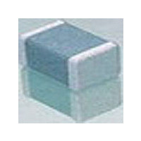
160R15X106KV4E Johanson, 160R15X106KV4E Datasheet

160R15X106KV4E
Manufacturer Part Number
160R15X106KV4E
Description
Manufacturer
Johanson
Datasheet
1.160R15X106KV4E.pdf
(2 pages)
Specifications of 160R15X106KV4E
Tolerance (+ Or -)
10%
Voltage
16VDC
Temp Coeff (dielectric)
X5R
Operating Temp Range
-55C to 85C
Mounting Style
Surface Mount
Construction
SMT Chip
Case Style
Ceramic Chip
Failure Rate
Not Required
Wire Form
Not Required
Product Length (mm)
2.03mm
Product Depth (mm)
1.27mm
Product Height (mm)
1.52mm
Product Diameter (mm)
Not Requiredmm
Capacitance
10uF
Package / Case
0805
Lead Free Status / RoHS Status
Compliant
Available stocks
Company
Part Number
Manufacturer
Quantity
Price
Company:
Part Number:
160R15X106KV4E
Manufacturer:
Johanson
Quantity:
46 000
16
T
H
500 = 50 V
250 = 25 V
160 = 16 V
100 = 10 V
6R3 = 6.3 V
ANCERAM
OW TO
0.01
VOLTAGE
0.1
10
250
0.001
1
P/N written: 250R18Y105ZV4E
• Switching Power Supply Smoothing (Input/Output)
• DC/DC Converter Smoothing (Input/Output)
O
RDER
0.01
CASE SIZE
Typical ESR Comparison
See Chart
®
TANCERAM
R18
C
Frequency (MHz)
HIP
0.1
1.0 μF / 16V TANCERAM
C
1.0 μF / 16V Tantalum
DIELECTRIC
®
APACITORS
W = X7R
X = X5R
Y = Y5V
1
Y
10
www.johanson dielectrics.com
1st two digits are
significant; third digit
denotes number of
zeros.
®
474 = 0.47 µF
105 = 1.00 µF
CAPACITANCE
105
100
A
PPLICATIONS
TANCERAM
in many applications and offer several key advantages over
traditional tantalums. Because Tanceram
extremely low ESR, equivalent circuit performance can often
be achieved using considerably lower capacitance values.
Low DC leakage reduces current drain, extending the battery
life of portable products. Tancerams
voltage ratings offer improved reliability and eliminate large
voltage de-rating common when designing with tantalums.
A
• Low ESR
• Higher Surge Voltage
• Reduced CHIP Size
• Higher Insulation Resistance
DVANTAGES
M = ±20%
Z = +80% -20%
K = ±10%
TOLERANCE
X7R/X5R
100%
Y5V
75%
50%
25%
Z
®
0%
chip capacitors can replace tantalum capacitors
0
• Backlighting Inverters
• General Digital Circuits
Typical Breakdown Voltage Comparison
100
V = Ni barrier w/
100% Sn Plating
TERMINATION
4 = Unmarked
MARKING
1.0 μF / 16V TANCERAM
1.0 μF / 16V
Tantalum
DC Breakdown Voltage
V
200
• Low DC Leakage
• Non-polarized Devices
• Improved Reliability
• Higher Ripple Current
®
4
300
high DC breakdown
®
capacitors exhibit
conform to EIA RS481
Code
Tape specifications
E
T
TAPE MODIFIER
®
400
Plastic
Paper
Type Reel
E
7”
7”
500
Related parts for 160R15X106KV4E
160R15X106KV4E Summary of contents
Page 1
... Y5V significant; third digit Z = +80% -20% denotes number of X7R/X5R zeros ±10% 474 = 0.47 µ ±20% 105 = 1.00 µF www.johanson dielectrics.com ® capacitors exhibit ® high DC breakdown • Low DC Leakage • Non-polarized Devices • Improved Reliability • Higher Ripple Current 1.0 μF / 16V Tantalum ® ...
Page 2
... For ≤ 25 VDC: 10% max. 100 Ω GΩ, whichever is less 2.5 X WVDC, 25°C, 50mA max. Capacitance values ≤ 22 µF: 1.0kHz±50Hz @ 1.0±0.2 Vrms Capacitance values > 22 µF: 120Hz±10Hz @ 0.5V±0.1 Vrms See page 20 for additional dielectric specifications. www.johanson dielectrics.com S ELECTION 10 µF 22 µF 47 µF ...


