BFC246840334 Vishay, BFC246840334 Datasheet - Page 22
BFC246840334
Manufacturer Part Number
BFC246840334
Description
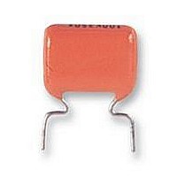
CAPACITOR, 0.33UF 630V CAPACITOR, 0.33UF 630V
Manufacturer
Vishay
Series
2222468r
Specifications of BFC246840334
Capacitance
.33uF
Tolerance (+ Or -)
10%
Voltage
630VDC/250VAC
Temp Coeff (dielectric)
PLYE
Mounting Style
Through Hole
Construction
Radial
Failure Rate
Not Required
Seated Plane Height
23mm
Product Diameter (mm)
Not Requiredmm
Product Height (mm)
23mm
Product Depth (mm)
10mm
Product Length (mm)
26mm
Lead Spacing (nom)
22.5mm
Lead Diameter (nom)
0.8mm
Operating Temp Range
-55C to 105C
Package / Case
Not Required
Voltage Rating, Ac
250V
Voltage Rating, Dc
630V
Capacitor Dielectric Type
POLYESTER
Tolerance,
10%
Tolerance, -
10%
Temp, Op. Max
85(DEGREE C)
Rohs Compliant
YES
Tolerance
10 %
Voltage Rating
630 Volts
Termination Style
Radial
Lead Spacing
22.5 mm
Product
Metallized Polyester Film Capacitors
Lead Free Status / RoHS Status
Compliant
Lead Free Status / RoHS Status
Compliant


MKT 467, MKT 468, MKT 469
Vishay BCcomponents
POWER DISSIPATION AND MAXIMUM COMPONENT TEMPERATURE RISE
The power dissipation must be limited in order not to exceed the maximum allowed component temperature rise as a function of
the free ambient temperature.
The power dissipation can be calculated according type detail specification “HQN-384-01/101: Technical Information Film
Capacitors”.
The component temperature rise (ΔT) can be measured (see section “Measuring the component temperature” for more details)
or calculated by ΔT = P/G:
MEASURING THE COMPONENT TEMPERATURE
A thermocouple must be attached to the capacitor body as in:
The temperature is measured in unloaded (T
The temperature rise is given by ΔT = T
To avoid radiation or convection, the capacitor should be tested in a wind-free box.
APPLICATION NOTE AND LIMITING CONDITIONS
These capacitors are not suitable for mains applications as across-the-line capacitors without additional protection, as described
hereunder. These mains applications are strictly regulated in safety standards and therefore electromagnetic interference
suppression capacitors conforming the standards must be used.
To select the capacitor for a certain application, the following conditions must be checked:
1. The peak voltage (U
2. The peak-to-peak voltage (U
www.vishay.com
72
• ΔT = Component temperature rise (°C)
• P = Power dissipation of the component (mW)
• G = Heat conductivity of the component (mW/°C)
W
(mm)
12.0
12.5
13.0
13.5
14.0
14.5
15.0
15.5
16.0
max.
P
) shall not be greater than the rated DC voltage (U
P-P
) shall not be greater than 2
For technical questions, contact: dc-film@vishay.com
C
- T
PITCH 10 mm
amb
MKT Radial Lacquered Type
amb
.
) and maximum loaded condition (T
-
-
-
-
-
-
-
-
-
DC Film Capacitors
√
PITCH 15.5 mm
2 x U
HEAT CONDUCTIVITY (mW/°C)
Rac
-
-
-
-
-
-
-
-
-
to avoid the ionisation inception level
Rdc
)
Thermocouple
C
).
PITCH 22.5 mm
-
-
-
-
-
-
-
-
-
Document Number: 28105
PITCH 27.5 mm
Revision: 08-Dec-08
27.0
30.0
30.0
30.0
30.0
33.0
33.0
37.0
37.0
Related parts for BFC246840334
Image
Part Number
Description
Manufacturer
Datasheet
Request
R

Part Number:
Description:
357-036-542-201 CARDEDGE 36POS DL .156 BLK LOPRO
Manufacturer:
Vishay
Datasheet:
Part Number:
Description:
357-036-542-201 CARDEDGE 36POS DL .156 BLK LOPRO
Manufacturer:
Vishay
Datasheet:
Part Number:
Description:
357-036-542-201 CARDEDGE 36POS DL .156 BLK LOPRO
Manufacturer:
Vishay
Datasheet:
Part Number:
Description:
357-036-542-201 CARDEDGE 36POS DL .156 BLK LOPRO
Manufacturer:
Vishay
Datasheet:
Part Number:
Description:
357-036-542-201 CARDEDGE 36POS DL .156 BLK LOPRO
Manufacturer:
Vishay
Datasheet:
Part Number:
Description:
357-036-542-201 CARDEDGE 36POS DL .156 BLK LOPRO
Manufacturer:
Vishay
Datasheet:
Part Number:
Description:
357-036-542-201 CARDEDGE 36POS DL .156 BLK LOPRO
Manufacturer:
Vishay
Datasheet:
Part Number:
Description:
357-036-542-201 CARDEDGE 36POS DL .156 BLK LOPRO
Manufacturer:
Vishay
Datasheet:
Part Number:
Description:
357-036-542-201 CARDEDGE 36POS DL .156 BLK LOPRO
Manufacturer:
Vishay
Datasheet:
Part Number:
Description:
357-036-542-201 CARDEDGE 36POS DL .156 BLK LOPRO
Manufacturer:
Vishay
Datasheet:
Part Number:
Description:
357-036-542-201 CARDEDGE 36POS DL .156 BLK LOPRO
Manufacturer:
Vishay
Datasheet:
Part Number:
Description:
357-036-542-201 CARDEDGE 36POS DL .156 BLK LOPRO
Manufacturer:
Vishay
Datasheet:
Part Number:
Description:
357-036-542-201 CARDEDGE 36POS DL .156 BLK LOPRO
Manufacturer:
Vishay
Datasheet:
Part Number:
Description:
357-036-542-201 CARDEDGE 36POS DL .156 BLK LOPRO
Manufacturer:
Vishay
Datasheet:
Part Number:
Description:
357-036-542-201 CARDEDGE 36POS DL .156 BLK LOPRO
Manufacturer:
Vishay
Datasheet: