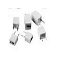
184154J100ABA-F Cornell Dubilier Electronics (CDE), 184154J100ABA-F Datasheet - Page 2

184154J100ABA-F
Manufacturer Part Number
184154J100ABA-F
Description
Manufacturer
Cornell Dubilier Electronics (CDE)
Datasheet
1.184154J100ABA-F.pdf
(4 pages)
Specifications of 184154J100ABA-F
Tolerance (+ Or -)
5%
Voltage
100VDC/63VAC
Temp Coeff (dielectric)
PLYE
Mounting Style
Through Hole
Construction
Radial
Failure Rate
Not Required
Seated Plane Height
9mm
Product Diameter (mm)
Not Requiredmm
Product Height (mm)
9mm
Product Depth (mm)
4mm
Product Length (mm)
10.5mm
Lead Spacing (nom)
7.5mm
Lead Diameter (nom)
0.6mm
Operating Temp Range
-55C to 125C
Capacitance
.15uF
Package / Case
Not Required
Lead Free Status / RoHS Status
Compliant
CDE Cornell Dubilier 1605 E. Rodney French Blvd. New Bedford, MA 02744 Phone: (508)996-8561 Fax: (508)996-3830 www.cde.com
Type 167/184
Lead length shown is as supplied on 167 Series
Ratings
# Indicates packaging type: R = Tape and Reel, A = Ammo Pack
> Indicates tooling code: A = 16.5 mm, B = 18.5 mm, C = 16.0 mm (See H dimension in taping specifications)
* Indicates capacitance tolerance: J = ±5%, K = ±10%, M = ±20%
Capacitor Outline Drawing
Test Conditions
Performance
Soldering Temperature
Soldering Duration
Capacitance Change
DF Change tg
Insulation Resistance
Cap
.068
1.00
.033
.047
.068
(µF)
.15
.22
.33
.10
.15
.22
.27
.33
.47
.68
.10
.12
(±0.4 mm)
±.015
167124*100B–F
167154*100B–F
167224*100C–F 184224*100#C>–F
167334*100C–F 184334*100#C>–F
167333*100A–F
167473*100A–F
167683*100A–F
167104*100A–F
167684*63C–F
167105*63C–F
167683*63A–F
167104*63A–F
167154*63A–F
167224*63A–F
167274*63A–F
167334*63A–F
167474*63B–F
Max
Part Number
S
L
Catalog
C/C
Ød ±.003
Metallized Polyester Radial Lead Capacitors
Soldering
Max
260 ºC ±5 ºC
10 sec ±1 sec
(±0.076)
H
30 x 10
184333*100#A>–F
184473*100#A>–F
184683*100#A>–F
184104*100#A>–F
184124*100#B>–F
184154*100#B>–F
±2%
limit value
184334*63#A>–F
184474*63#B>–F
184684*63#C>–F
184105*63#C>–F
184683*63#A>–F
184104*63#A>–F
184154*63#A>–F
184224*63#A>–F
184274*63#A>–F
Ammo Pack
Tape & Reel
–4
Max
at 10 kHz
T
(5.5 ±1.0 mm)
.
217 ±.039
0.413
0.413
0.413
0.413
0.413
0.413
0.413
0.413
0.413
0.413
0.413
0.413
0.413
0.413
0.413
0.413
0.413
L
100 Vdc / 63 Vac
63 Vdc / 40 Vac
0.138
0.138
0.138
0.138
0.138
0.138
0.157
0.197
0.197
0.138
0.138
0.138
0.138
0.157
0.157
0.197
0.197
T
Inches
0.276
0.276
0.276
0.354
0.354
0.433
0.433
0.276
0.276
0.276
0.276
0.276
0.276
0.354
0.433
0.433
0.276
Test Conditions
Performance
Test Conditions
Performance
Test Conditions
Performance
H
For Vn > 100 Vdc
For Vn
Temperature
Relative Humidity
Test Duration
Capacitance Change
DF Change tg
Insulation Resistance
Temperature
Test Duration
Voltage Applied
Capacitance Change
DF Change tg
Insulation Resistance
Temperature
Voltage Charge Time
Voltage Charge
0.295
0.295
0.295
0.295
0.295
0.295
0.295
0.295
0.295
0.295
0.295
0.295
0.295
0.295
0.295
0.295
0.295
S
Test Method and Performance
100 Vdc
0.024
0.024
0.024
0.024
0.024
0.024
0.024
0.024
0.024
0.024
0.024
0.024
0.024
0.024
0.024
0.024
0.024
Ød
Insulation Resistance
10.5
10.5
10.5
10.5
10.5
10.5
10.5
10.5
10.5
10.5
10.5
10.5
10.5
10.5
10.5
10.5
10.5
Damp Heat Test
C/C
C/C
L
Life Test
25 ºC ±5 ºC
1 minute
50 Vdc for Vn < 100 Vdc
100 Vdc for Vn
+40 ºC
95%
21 days
+85 ºC
1000 hrs
1.25 x Vn
30,000 M
50 x 10
30 x 10
±5%
±5%
50% of limit value
50% of limit value
3.5
3.5
3.5
3.5
3.5
3.5
4.0
5.0
5.0
3.5
3.5
3.5
3.5
4.0
4.0
5.0
5.0
0,000 M
,000 M
T
Millimeters
4
–4
11.0
11.0
11.0
11.0
RoHS Compliant
at 1 kHz
7.0
7.0
7.0
7.0
7.0
9.0
7.0
7.0
7.0
7.0
9.0
9.0
7.0
at 10 kHz
H
x µF for
for C
(50,000 M
100 Vdc
7.5
7.5
7.5
7.5
7.5
7.5
7.5
7.5
7.5
7.5
7.5
7.5
7.5
7.5
7.5
7.5
7.5
S
0.1µF
0.1µF
typical)
0.6
0.6
0.6
0.6
0.6
0.6
0.6
0.6
0.6
0.6
0.6
0.6
0.6
0.6
0.6
0.6
0.6
Ød


