CR200L.5 BI Technologies, CR200L.5 Datasheet
CR200L.5
Manufacturer Part Number
CR200L.5
Description
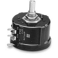
Potentiometers 1-13/16 200 OHM 3 TURN
Manufacturer
BI Technologies
Type
WireWound Precision Potentiometerr
Specifications of CR200L.5
Resistance
200 Ohms
Tolerance
3 %
Power Rating
3 Watts
Termination Style
Lug
Taper
Linear
Number Of Turns
3
Element Type
Wire Wound
Shaft Type
Round / Plain
Shaft Length
20.6 mm
Shaft Diameter
6.35 mm
Operating Temperature Range
- 65 C to + 85 C
Mounting Style
Panel
Lead Free Status / RoHS Status
Compliant


MODEL CR SERIES
Single-In-Line
Conformal Coated
Resistor/Capacitor
Networks
FEATURES
• 4 to 14 Leads
• Standard and custom circuits
• Space saving design
ELECTRICAL (CAPACITOR)
DIELECTRIC TABLE
ELECTRICAL (RESISTOR)
Power Dissipation, Watts, at 70°C
Operating Voltage, Maximum
Standard Resistance Range, Ohms
Standard Resistance Tolerance
Temperature Coefficient of Resistance
Operating Temperature Range
Dielectric
SL
X7R
Y5V
CG (NPO)
Specifications subject to change without notice.
Rated Voltage
Capacitance Range
Tolerance
Temperature Coefficient
Operating Temperature Range
(% of Change)
Code
S
X
Y
CG
J Tol.
±5%
Characteristics
+350/-1,000/°C
±15% (-55 to +125°C)
+22% to -82% (-30 to +85°C)
±30ppm/°C
4-29
G. Tol.
K Tol.
±10%
±2%
10pF to 470,000pF (Custom 2.2pF to 10pF max.)
CG, SL & X7R: -55°C to +125°C
M Tol.
±20%
J Tol.
±5%
Values
10pF to 3,300pF
680pF to 47nF
10pF to 1,500pF
10pF to 1,500pF
Refer to Dielectric Table
Model CR Series
25Vdc, 50Vdc, 100Vdc
1/8 to 1/4 per resistor
Y5V: -30°C to +85°C
100 to 300ppm/°C
-55°C to +125°C
+80% to -20%
10 to 2.2 Meg
±10%
K Tol.
Z Tol.
100Vdc
4
Related parts for CR200L.5
Image
Part Number
Description
Manufacturer
Datasheet
Request
R

Part Number:
Description:
Manufacturer:
BI Technologies
Datasheet:
Part Number:
Description:
Dual In-Line Thick Film Resistor Network
Manufacturer:
BI Technologies
Part Number:
Description:
Manufacturer:
BI Technologies
Datasheet:
Part Number:
Description:
Manufacturer:
BI Technologies
Datasheet:
Part Number:
Description:
Manufacturer:
BI Technologies
Datasheet:
Part Number:
Description:
Manufacturer:
BI Technologies
Datasheet:
CR200L.5 Summary of contents
Page 1
MODEL CR SERIES Single-In-Line Conformal Coated Resistor/Capacitor Networks FEATURES • Leads • Standard and custom circuits • Space saving design ELECTRICAL (CAPACITOR) Rated Voltage Capacitance Range Tolerance Temperature Coefficient (% of Change) Operating Temperature Range ELECTRICAL (RESISTOR) ...
Page 2
SCHEMATICS -A Circuit ... n-2 n Circuit ... n-2 n ...
Page 3
OUTLINE DIMENSIONS (Inch/mm) .100(2.54mm .050(1.27mm) Max Leads .100±.010 2.54±0.25 TYPICAL PART MARKING .130 Max. 3.3 .300 Max. 7.62 .138±0.03 3.5±0.8 CR8 - A - 001 Logo Lead #1 Model Date Code Indicator 4-31 ...
Page 4
ORDERING INFORMATION 101 J 101 Model Series No. of Leads pins Circuit Type Resistance Code: 101 = 100 Resistance Tolerance and TCR 2%, TCR = 100ppm ...