HLZ03306ZR0500KS Vishay, HLZ03306ZR0500KS Datasheet

HLZ03306ZR0500KS

Manufacturer Part Number
HLZ03306ZR0500KS
Description
Manufacturer
Vishay
Type
Wirewoundr
Datasheet

Specifications of HLZ03306ZR0500KS

Power Rating(s)
35W
Tolerance (+ Or -)
10%
Mounting Style
Bolt-On
Construction
Tubular Corrugated
Operating Temp Range
-55C to 350C
Case Style
Ceramic Hi Temp Sil
Termination Style
Radial Lug
Military Standard
Not Required
Failure Rate
Not Required
Product Length (mm)
50.8mm
Product Height (mm)
28.58mm
Product Depth (mm)
14.29mm
Lead Free Status / RoHS Status
Not Compliant
HLZ
Vishay Dale
MATERIAL SPECIFICATIONS
Element: Copper-nickel alloy of nickel-chrome alloy,
depending on resistance range
Core: Ceramic, steatite
Coating: Special high temperature silicone
Standard Terminals: Model “Z” terminals are tinned steel
Terminal Bands: Steel
Part Marking: DALE, model, wattage, value, tolerance, date
code
* Pb containing terminations are not RoHS compliant, exemptions may apply
www.vishay.com
86
additional P/N’s)
STANDARD ELECTRICAL SPECIFICATIONS
GLOBAL
MODEL
HLZ033
HLZ090
HLZ099
HLZ105
HLZ110
HLZ140
HLZ165
HLZ220
HLZ240
HLZ275
HLZ300
HLZ375
TECHNICAL SPECIFICATIONS
PARAMETER
Temperature Coefficient
Dielectric Withstanding Voltage
Short Time Overload
Maximum Working Voltage
Insulation Resistance
Operating Temperature Range
GLOBAL PART NUMBER INFORMATION
New Global Part Numbering: HLZ16506Z10R00KJ (preferred part number format)
(See “Standard
Historical Part Number Example: HLZ-165-06Z 10 Ω 10 % J01 (will continue to be accepted)
Specifications”
table above for
HISTORICAL MODEL
GLOBAL
Electrical
MODEL
HLZ165
H
HLZ-165
L
DESIGNATION
HISTORICAL
MODEL
HLZ-33
HLZ-90
HLZ-99
HLZ-105
HLZ-110
HLZ-140
HLZ-165
HLZ-220
HLZ-240
HLZ-275
HLZ-300
HLZ-375
TERMINAL
Z
06
07
15
1
TERMINAL/FINISH
ppm/°C
UNIT
V
6
°C
Ω
V
AC
-
Z = Tin/lead
TERMINAL
N = Nickel
E = Lead
(Pb)-free
Industrial Power, Edgewound
FINISH
06Z
For technical questions, contact: ww2bresistors@vishay.com
POWER RATING P
5
Wirewound Resistors,
0
10R00 = 10.0 Ω
100
105
110
140
165
220
240
275
300
375
K = Thousand
35
90
RESISTANCE
1K000 = 1 kΩ
W
R = Decimal
VALUE
± 90 for 0.1 Ω to 0.99 Ω; ± 50 for 1 Ω to 9.9 Ω; ± 30 for 10 Ω and above
6
RESISTANCE VALUE
25 °C
1000 MΩ minimum dry, 100 MΩ minimum after moisture test
Z
10 Ω
* Tin/lead for type “Z”, lead (Pb)-free for type “N”
TOLERANCE
K = ± 10.0 %
1000, from terminal to mounting hardware
J = ± 5.0 %
HLZ RESISTOR CHARACTERISTICS
1
FEATURES
• High temperature silicon coating
• Complete welded construction
• Excellent for intermittent power and pulsing
• Designed to meet heavy-duty requirement
• Excellent stability in operation (< 3 % change in
± 10 % standard, ± 5 % available
applications
where space is at a premium
resistance)
10 x rated power for 5 s
RESISTANCE RANGE Ω
0
Derating
120
100
- 55 to + 350
80
60
40
20
0
(P x R)
- 65
0.35 - 13.0
0.10 - 16.0
0.10 - 18.0
0.15 - 23.0
0.15 - 25.0
0.20 - 32.0
R
0.05 - 1.9
0.10 - 5.7
0.15 - 6.1
0.20 - 7.4
0.20 - 8.6
0.08 - 9.0
E = Lead (Pb)-free skin pack
TOLERANCE
PACKAGING CODE
J* = Skin pack (J01)
1/2
0
0
10 %
25
50
AMBIENT TEMPERATURE IN °C
0
150
K
Document Number: 30245
J
250
PACKAGING
WEIGHT (typical)
Revision: 13-Jul-07
(Dash Number)
(up to 2 digits)
as applicable
J01
From 1 - 99
SPECIAL
109
163
186
224
236
286
18
36
41
49
54
91
g
350
RoHS*
COMPLIANT
Available
Pb-free
e3

Related parts for HLZ03306ZR0500KS

HLZ03306ZR0500KS Summary of contents

Page 1

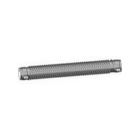
... Historical Part Number Example: HLZ-165-06Z 10 Ω J01 (will continue to be accepted) HLZ-165 06Z HISTORICAL MODEL TERMINAL/FINISH * Pb containing terminations are not RoHS compliant, exemptions may apply www.vishay.com For technical questions, contact: ww2bresistors@vishay.com 86 Wirewound Resistors, FEATURES • High temperature silicon coating • Complete welded construction • Excellent for intermittent power and pulsing applications • ...

Page 2

... C [19.05] [19.05] 1.375 1.750 B [34.93] [44.45] Document Number: 30245 For technical questions, contact: ww2bresistors@vishay.com Revision: 13-Jul-07 Wirewound Resistors, Industrial Power, Edgewound DISTANCE TERMINAL BETWEEN SETBACK I.D. TERMINALS ± 0.031 [± 0.79] ± 0.031 [± 0.79] (REF.) ...

Page 3

... Vishay disclaims any and all liability arising out of the use or application of any product described herein or of any information provided herein to the maximum extent permitted by law. The product specifications do not expand or otherwise modify Vishay’ ...

Related keywords