97-3106A-14S-9P Amphenol, 97-3106A-14S-9P Datasheet - Page 23
97-3106A-14S-9P
Manufacturer Part Number
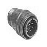
97-3106A-14S-9P
Description
Circular MIL / Spec Connectors 14S-9P PIN
Manufacturer
Amphenol
Type
MIL-C-5015 Circularr
Series
97 Seriesr
Specifications of 97-3106A-14S-9P
Contact Gender
PIN
Gender
PL
Number Of Contacts
2POS
Shell Size / Insert Arrangement
14S-9
Mounting Style
Cable
Termination Method
Solder
Shell Plating
Olive Drab Cadmium
Contact Plating
Silver
Body Orientation
Straight
Strain Relief
No
Contact Classification
2Signal
Operating Temp Range
-55C to 125C
Product Diameter (mm)
28.58mm
Product Length (mm)
37.13mm
Mil Type
MIL-DTL-5015
Product Type
Connectors
Contact Style
Pin (Male)
Shell Style
Plug
Shell Size
14S
Insert Arrangement
14S-9
Mating Style
Threaded
Termination Style
Solder
Body Material
Aluminum Alloy
Mounting Angle
Straight
Lead Free Status / RoHS Status
Not Compliant


97 series crimp type
specifications, insert availability,
alternate insert positioning
Specifications
Standard shell finish - clear chromate over cadmium plate
(optional plating available, see how to order page 27).
Inserts - molded of a 94V-O Underwriters Laboratory rated
material.
Contacts - copper alloy formed, silver plated (gold plating is
also available, see how to order page 28).
Wire sizes - 12 AWG through 30 AWG.
All constructions perform satisfactorily from –55°C to
+125°C ( –67°F to +257°F).
Insert Availability
10SL-3
10SL-4
12S-3
14S-1
14S-2
14S-5
14S-7
16S-1
16S-8
18-1
18-4
18-11
18-12
18-19
18-20
20-4
20-7
20-27
20-29
22-14
24-2
28-11
28-12
28-20
28-21
32-414
36-10
Number
Insert
Contacts
Total
10
10
14
17
19
22
26
14
37
52
48
3
2
2
3
4
5
3
7
5
4
5
6
5
4
8
7
1/16
1/16
1/16
1/16
1/16
1/16
1/16
1/16
1/8
1/16
1/16
1/16
1/16
1/8
1/8
1/16
1/16
1/16
1/16
1/8
1/16
1/16
1/16
1/16
1/16
1/16
Inches
Mechanical
Spacing
1.57
1.57
1.57
1.57
1.57
1.57
1.57
1.57
3.18
1.57
1.57
1.57
1.57
3.18
3.18
1.57
1.57
1.57
1.57
3.18
1.57
1.57
1.57
1.57
1.57
1.57
mm
Service
INST.
INST.
INST.
Rating
D
D
D
D
A
A
A
A
A
A
A
A
A
A
A
A
A
A
A
A
A
A
A
A
A
A
Contact Size
10
12
5
4
7
4
10
14
17
19
18
26
37
52
48
16
3
2
2
3
4
5
3
7
5
4
6
4
6
5
4
4
4
21
Alternate Insert Positioning
* Rotates opposite above illustration.
Arrangement
12S-3
14S-2
14S-5
14S-7
16S-1
16S-8
18-1
18-4
18-11
18-12
18-19
18-20
20-4
20-7
20-27
20-29
22-14
24-2
28-9
28-11
28-12
28-20
28-21
32-8
32-414*
36-10
Insert
FRONT FACE OF PIN INSERT
80*
70
90
80
70
35
80
90
45
80
35
80
80
80
80
80
90
80
80
80
80
W
–
–
–
–
–
W
X
110*
145
120
110
180
170
145
110
170
120
180
110
110
110
110
110
180
110
110
125
125
–
–
–
–
–
C L
X
normal
Degrees
Y
Z
250*
215
240
270
265
215
250
265
240
270
250
250
250
250
250
270
250
250
235
235
–
–
–
–
–
–
Y
280*
290
280
290
325
280
280
325
280
280
280
280
280
280
280
280
280
–
–
–
–
–
–
–
–
–
Z
Related parts for 97-3106A-14S-9P
Image
Part Number
Description
Manufacturer
Datasheet
Request
R

Part Number:
Description:
97 SERIES STRAIGHT PLUG,SOLID BACK SHELL, 18 SHELL SIZE, 22 INSERT CONGF. NUMBER
Manufacturer:
Amphenol Industrial Operations
Datasheet:

Part Number:
Description:
Circular MIL / Spec Connectors SZ 24 BLACK SHELL
Manufacturer:
Amphenol
Datasheet:
Part Number:
Description:
Circular Connector Body Material:Aluminum Alloy
Manufacturer:
Amphenol Industrial Operations
Datasheet:
Part Number:
Description:
Circular Connector Body Material:Aluminum Alloy
Manufacturer:
Amphenol Industrial Operations
Datasheet:
Part Number:
Description:
Circular Connector Body Material:Aluminum Alloy
Manufacturer:
Amphenol Industrial Operations
Datasheet:

Part Number:
Description:
Cable Specification: PU CABLE, UL20549 24AWG*8C+AD,OD= 6.0mm
Manufacturer:
Amphenol