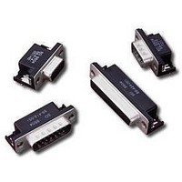
56-424-001 Spectrum Control, 56-424-001 Datasheet - Page 20

56-424-001
Manufacturer Part Number
56-424-001
Description
D-Subminiature Connectors 25 PIN FEMALE
Manufacturer
Spectrum Control
Type
Filtered D-Subr
Datasheet
1.56-424-001.pdf
(104 pages)
Specifications of 56-424-001
Number Of Contacts
25POS
Number Of Terminals
25
Plug / Receptacle
SKT
Contact Plating
Gold Over Nickel
Contact Pitch (mm)
2.76mm
Body Orientation
Right Angle
Mounting Style
Through Hole
Number Of Ports
1Port
Number Of Contact Rows
2
Operating Temp Range
-40C to 105C
Termination Method
Solder
Current Rating
5A
Housing Material
Steel
Contact Material
Phosphor Bronze
Product Length (mm)
53.04mm
Product Depth (mm)
19.2mm
Product Height (mm)
12.55mm
Product
Filtered Hoods & Connectors
Number Of Positions / Contacts
25
Shell Plating
Tin
Gender
Female
Mounting Angle
Right
Termination Style
Solder Pin
Operating Temperature Range
- 40 C to + 105 C
Lead Free Status / RoHS Status
Not Compliant
Available stocks
Company
Part Number
Manufacturer
Quantity
Price
Company:
Part Number:
56-424-001
Manufacturer:
API Technologies Corp
Quantity:
457
147
Hi-Density Filtered Adapter
for Telecommunications
Within the telecommunications industry, it has been
standard practice to use an adapter (male/female) type
of EMI filtered connector as the interface between the
switching system electronics and the premise wiring.
These filtered adapters provide effective containment
of EMI compared to either D-subminiature or 50-position
“ribbon” contact type connectors.
development of a new generation of filtered adapters.
Special Requirements
s
s
s
s
s
Spectrum Control, in response to these unique
requirements of the telecommunication industry,
has developed a new Hi-Density filtered adapter.
Features
s
s
s
s
s
SPECTRUM CONTROL INC. • 8031 Avonia Rd. • Fairview, PA 16415 • Phone: 814-474-2207 • Fax: 814-474-2208 • Web site: www.spectrumcontrol.com
SPECTRUM CONTROL GmbH • Hansastrasse 6 • 91126 Schwabach, Germany • Phone: (49)-9122-795-0 • Fax: (49)-9122-795-58
Higher density wiring
The need for more contacts, usually
a multiple of 16
Higher reliability contact geometries
Bellcore TR-NWT-001089 requirements
s
s
Improved flammable resistant plastic insulators
New ceramic technology and filter element
construction to accept higher voltages
Improved reliability compared to “ribbon”
type connectors
Integral ground plane and one-piece diecast
housing for the highest level of EMI integrity
More contacts/wires per square inch of panel space
through Hi-Density arrangements
64 contact positions standard, with 78 positions
available by request in any filter combination
The following several factors have mandated the
1000 volts AC withstand for one minute
2500 volts spike surge testing
Mechanical Specifications
Shell . . . . . . . . . . . . Zinc diecast, nickel plated
Insulators . . . . . . . . Thermoplastic, UL94V-0
Contacts . . . . . . . . . One-piece, screw machined
Ground Plane . . . . . Brass, solder plated
Grounding
Springs . . . . . . . . . . Beryllium copper, tin plated per
Operating
Temperature. . . . . . . -55°C to +125°C
Capacitor. . . . . . . . . High performance ceramic
Electrical Specifications
Rated Voltage. . . . . . 100 VDC
Current
Rating . . . . . . . . . . . 3 Amps
DC Resistance . . . . . 15 milliohm max.
Dielectric
Withstanding
Voltage . . . . . . . . . . 1000 VRMS (FCC Part 68 test)
Capacitance . . . . . . . 1000 pF, ±25%
Voltage Surge . . . . . meets 2500 volts surge (10/1000)
. . . . . . . . . . . . . . . .
. . . . . . . . . . . . . . . .
. . . . . . . . . . . . . . . .
. . . . . . . . . . . . . . . .
. . . . . . . . . . . . . . . .
. . . . . . . . . . . . . . . .
. . . . . . . . . . . . . . . .
. . . . . . . . . . . . . . . .
. . . . . . . . . . . . . . . .
150 µ inches (3.81 µm) min.
Copper alloy, contact area plated
50 µ inches (1.27 µm) gold
over 50 µ inches (1.27 µm) nickel
MIL-T-10727
feed-thru utilizing ultra low
ESR design
(See Wave form figure on
next page)


