56F414-001 Spectrum Control, 56F414-001 Datasheet - Page 55
56F414-001
Manufacturer Part Number
56F414-001
Description
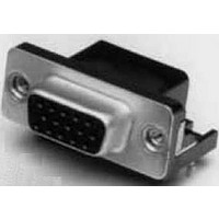
CONNECTOR, D SUB FLTR, RECEPTACLE, 15POS
Manufacturer
Spectrum Control
Type
Filtered D-Subr
Series
Fr
Specifications of 56F414-001
Number Of Contacts
15POS
Number Of Terminals
15
Plug / Receptacle
SKT
Contact Plating
Gold Over Nickel
Contact Pitch (mm)
2.74mm
Body Orientation
Right Angle
Mounting Style
Through Hole
Number Of Ports
1Port
Number Of Contact Rows
2
Operating Temp Range
-40C to 105C
Termination Method
Solder
Current Rating
5A
Housing Material
Steel
Contact Material
Phosphor Bronze
Product Length (mm)
39.14mm
Product Depth (mm)
19.2mm
Product Height (mm)
12.55mm
No. Of Contacts
15
D Sub Shell Size
DA
Connector Body Material
Metal
Gender
Receptacle
Contact Termination
Right Angle Through Hole
Connector Type
Filtered D Sub
Peak Reflow Compatible (260 C)
No
Rohs Compliant
Yes
Lead Free Status / RoHS Status
Compliant
Available stocks
Company
Part Number
Manufacturer
Quantity
Price
Company:

Part Number:
56F414-001
Manufacturer:
API Technologies Corp
Quantity:
457
Company:
Part Number:
56F414-001-HD
Manufacturer:
API Technologies Corp
Quantity:
457


Series E (ESD/EFT)
Transient Protected Connectors
Ordering Information
Example:
Integrated
D-sub
Connectors
Board Layouts
SPECTRUM CONTROL INC. • 8031 Avonia Rd. • Fairview, PA 16415 • Phone: 814-474-2207 • Fax: 814-474-2208 • Web site: www.spectrumcontrol.com
SPECTRUM CONTROL GmbH • Hansastrasse 6 • 91126 Schwabach, Germany • Phone: (49)-9122-795-0 • Fax: (49)-9122-795-58
Transient Voltage Protection with Capacitance
Immunity to IEC 61000-4-2 (ESD) up to level 4 and IEC 61000-4-4 (EFT) air and contact discharge specifications.
Notes: Consult factory for custom capacitance values. Typical leakage at 25°C is <25 µA
Transient Voltage Protection without Significant Capacitance
Immunity to IEC 61000-4-2 (ESD) up to Level 4 air and contact discharge. Excellent for digital, high speed and high frequency signals.
(1.42)
.056
56 -
.318" and .405" Footprint Typical Layout
Voltage Code
Voltage Code
Working
(2.84)
.112
Working
003
005
009
012
014
018
026
030
P24
Series E
(ESD/EFT)
Connectors
56-E04-005-5-T
E 0 4
Shell Size/
Number of
Contacts
0 - 9 size
1 - 15 size
2 - 25 size
3 - 37 size
- Top View
.054 (1.385)
Voltage (V) DC
>30.0
Max. Working
VDC
A
12.0
14.0
18.0
26.0
30.0
Max. Working Voltage
3.5
5.5
9.0
.109 (2.77)
24.0
-
Contact Type/Termination
1 - Pin to solder cup
2 - Pin to right angle
3 - Socket to straight PCB
4 - Socket to right angle
5 - Adapter (pin to socket)
6 - Socket to solder cup
7 - Pin to straight PCB
Ø.043 (1.09)
005
>25.0
(8.08)
.318
Ø.120 (3.05)
VAC
10.0
14.0
20.0
25.0
2.5
4.0
6.5
9.0
or
Typical
Dimensions in inches (mm)
(10.20)
150.0
.405
Maximum leakage 50 µA at V
-
Clamp Voltage
Shell
Size ±.005 (±0.13)
Clamp Voltage
15
25
37
9
10.0@5A
15.5@5A
20.0@2A
25.0@2A
30.0@5A
40.0@5A
58.0@5A
65.0@2A
8 x 20 µ s
5
(24.99)
(33.32)
(47.04)
(63.50)
1.312
1.852
2.500
.984
A
Working
Voltage Code
See table below.
(Use 3-digit
code that
matches your
electrical
requirements)
Maximum
80.0
-
(2.84)
.112
.590" Footprint Typical Layout - Top View
Peak Current
8 x 20 µ s
(14.99)
.590
This part number represents a Series E connector with a shell size of 9
and a socket to right angle configuration. The maximum working voltage
is 5.5 VDC and the connector has a .590" footprint with 4-40 threads.
120
120
120
120
100
T
40
40
30
m(DC)
Please consult factory for availability
Footprint
(right angle
connectors
only)
3 - .318"
4 - .405"
5 - .590"
Voltage
Trigger
1000
18 (15.9-20.3)
34 (29.5-38.5)
V breakdown
16 (14-18.5)
.054 (1.385)
5 (3.7-7.0)
8 (7.1-9.3)
12 (11-14)
25 (22-28)
42 (37-46)
1 ma
B
.109 (2.77)
Mounting or Hardware Options
GBL6 - for .062" boards
MIB - M3 thread on rear of flange
TIB - 4-40 thread on rear of flange
TIF - 4-40 thread on front of flange
GB - No board locks
GL - Includes grounding board lock
3G - 30µ" gold
5G - 50µ" gold
GJ - GL and jack screws
JS - Jack screws
Leakage (A)
M - M3 thread
T - 4-40 threads
_ - .120 thru-hole and 15µ" gold
_ - No GBL attached
J - Jack screws
Current
<1.0 nA
SC and Straight PCBs (only)
Right Angles and Adapters (only)
10 x 100 µ s
Energy (J)
Ø.043 (1.09)
(8.00)
(8.00)
0.3
0.3
0.1
0.1
0.3
0.3
0.3
0.1
Ø.120 (3.05)
.315
.315
Dimensions in inches (mm)
Shell
Typical Cap.
Size ±.005 (±0.13)
15
25
37
9
Typical Cap.
pF at 1 MHz
at 1 MHz
0.05 pF
2200
1600
450
350
480
450
190
80
(24.99)
(33.32)
(47.04)
(63.50)
1.312
1.852
2.500
.984
B
182
Related parts for 56F414-001
Image
Part Number
Description
Manufacturer
Datasheet
Request
R

Part Number:
Description:
Power Line Filters Single Stage
Manufacturer:
Spectrum Control Inc.
Datasheet:
Part Number:
Description:
High Current Single Line Feed-thru Filters
Manufacturer:
Spectrum Control Inc.
Datasheet:
Part Number:
Description:
Switched And Fused Filtered Power Entry Modules
Manufacturer:
Spectrum Control Inc.
Datasheet:
Part Number:
Description:
Surface Mount Emi Filters
Manufacturer:
Spectrum Control Inc.
Datasheet:

Part Number:
Description:
(PSMx Series) Surface Mount EMI Filters
Manufacturer:
Spectrum Control
Datasheet: