56-402-001 Spectrum Control, 56-402-001 Datasheet - Page 75
56-402-001
Manufacturer Part Number
56-402-001
Description
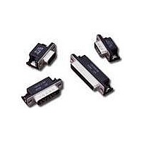
D-Subminiature Connectors 9 PIN MALE
Manufacturer
Spectrum Control
Type
Filtered D-Subr
Series
400r
Datasheet
1.56-402-001.pdf
(104 pages)
Specifications of 56-402-001
Number Of Contacts
9POS
Number Of Terminals
9
Plug / Receptacle
PIN
Contact Plating
Gold Over Nickel
Contact Pitch (mm)
2.74mm
Body Orientation
Right Angle
Mounting Style
Through Hole
Number Of Ports
1Port
Number Of Contact Rows
2
Operating Temp Range
-40C to 105C
Termination Method
Solder
Current Rating
5A
Housing Material
Steel
Contact Material
Brass
Product Length (mm)
30.81mm
Product Depth (mm)
19.1mm
Product Height (mm)
12.55mm
Product
Filtered Hoods & Connectors
Number Of Positions / Contacts
9
Shell Plating
Tin
Gender
Male
Mounting Angle
Right
Termination Style
Solder Pin
Operating Temperature Range
- 40 C to + 105 C
Connector Type
D-Sub Ferrite Filtered
Number Of Rows
2
Lead Free Status / RoHS Status
Not Compliant
Lead Free Status / RoHS Status
Not Compliant, Lead free / RoHS Compliant
Available stocks
Company
Part Number
Manufacturer
Quantity
Price
Company:

Part Number:
56-402-001
Manufacturer:
API Technologies Corp
Quantity:
457


202
Board & Panel Cutouts
Printed Circuit
Vertical Board Mount (standard density)
Board Layout (Pin and Socket Contact) for Standard D-Sub Connectors
Panel Cutouts (Front or Rear Mounting)
for Standard and Hi-Density D-Sub Connectors
Dimensions in inches (mm)
SPECTRUM CONTROL INC. • 8031 Avonia Rd. • Fairview, PA 16415 • Phone: 814-474-2207 • Fax: 814-474-2208 • Web site: www.spectrumcontrol.com
SPECTRUM CONTROL GmbH • Hansastrasse 6 • 91126 Schwabach, Germany • Phone: (49)-9122-795-0 • Fax: (49)-9122-795-58
15 (1)
25 (2)
37 (3)
50 (4)
Shell
Size
9 (0)
15 (1)
25 (2)
37 (3)
50 (4)
Shell
Size
9 (0)
(24.99)
(33.32)
(47.04)
(63.50)
(61.11)
±.015
1.312
1.852
2.500
2.406
(.38)
.984
A
E
D
(25.00)
(33.32)
(47.04)
(63.50)
(61.11)
1.312
1.852
2.500
2.406
.984
A
J
(12.49)
(16.66)
(23.52)
(31.75)
(30.55)
±.015
1.250
1.203
.492
.656
(.38)
.926
B
C
A
1.308 = 12 x .109
1.962 = 18 x .109
1.744 = 16 x .109
B
.436 = 4 x .109
.763 = 7 x .109
(11.07) (2.77)
(19.38) (2.77)
(33.22) (2.77)
(49.83) (2.77)
(44.30) (2.77)
2 rows
B
(19.74)
(28.07)
(41.78)
(58.24)
(55.63)
±.015
1.105
1.645
2.293
2.190
(.38)
.777
C
G
I
1.199 = 11 x .109
1.853 = 17 x .109
1.635 = 15 x .109
(14.03)
(20.89)
(29.12)
(27.81)
±.015
(9.87)
1.146
1.095
(.38)
.388
.552
.327 = 3 x .109
.654 = 6 x .109
.822
(16.61) (2.77)
(30.45) (2.77)
(47.07) (2.77)
(41.35) (2.77)
(8.31) (2.77)
D
F
1 row
C
(11.18)
(11.18)
(11.18)
(11.18)
(13.97)
H
±.003
.440
.440
.440
.440
.550
(.08)
E
(12.50)
(16.66)
(23.52)
(31.75)
(30.56)
1.250
1.203
(14.99)
.492
.656
.926
±.005
(5.59)
(5.59)
(5.59)
(5.59)
(6.98)
(.13)
.220
.220
.220
.220
.275
.590
D
F
(8.00)
.315
(2.77)
.109
±.002
Printed Circuit
Right Angle Mount (standard density)
(3.81)
(3.81)
(3.81)
(3.81)
(3.81)
.150
.150
.150
.150
.150
(.05)
E
G
(3.18 Dia.)
.125 Dia.
Front
Mounting
Panel Cutouts
(2.84)
2 holes
.112
F
D
E
Front of Flange
J
.056 (1.42)
.275 (6.99)
Rt Angle
2 rows
Mount
Mount
0.112
1 row
PCB
PCB
0.00
G
G
C
B
A
Panel
C
A
(3.18)
.125
H
D
B
Rear
Mounting
(Dia.)
10°
(1.14)
I
.045
I
F
F
E
(1.37)
.054
Panel
G
J
H
Related parts for 56-402-001
Image
Part Number
Description
Manufacturer
Datasheet
Request
R


Part Number:
Description:
USB CONNECTOR, RECEPTACLE, 4POS, THD
Manufacturer:
Spectrum Control
Datasheet:
Part Number:
Description:
USB CONNECTOR, RECEPTACLE, 4POS, THD
Manufacturer:
Spectrum Control
Datasheet:
Part Number:
Description:
USB CONNECTOR, RECEPTACLE, 4POS, THD
Manufacturer:
Spectrum Control
Datasheet:

Part Number:
Description:
Rotary Switch,STRAIGHT,Number Of Positions:3,PC TAIL Terminal,ROTARY SHAFT,PCB Hole Count:12
Manufacturer:
Grayhill Inc
Datasheet:

Part Number:
Description:
Power Line Filters Single Stage
Manufacturer:
Spectrum Control Inc.
Datasheet:
Part Number:
Description:
High Current Single Line Feed-thru Filters
Manufacturer:
Spectrum Control Inc.
Datasheet:
Part Number:
Description:
Switched And Fused Filtered Power Entry Modules
Manufacturer:
Spectrum Control Inc.
Datasheet:
Part Number:
Description:
Surface Mount Emi Filters
Manufacturer:
Spectrum Control Inc.
Datasheet:

Part Number:
Description:
(PSMx Series) Surface Mount EMI Filters
Manufacturer:
Spectrum Control
Datasheet: