201355-1 TE Connectivity, 201355-1 Datasheet - Page 80
201355-1
Manufacturer Part Number
201355-1
Description
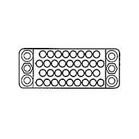
RECTANGULAR HOUSING, PLUG, 14WAY
Manufacturer
TE Connectivity
Type
Housingr
Series
Mr
Specifications of 201355-1
Number Of Contacts
14POS
Number Of Contact Rows
3
Body Orientation
Straight
Pitch (mm)
3.81mm
Gender
PL
Housing Material
Phenolic
Operating Temp Range
-55C to 150C
Housing Color
Black
Product Height (mm)
11.18mm
Product Depth (mm)
23.24mm
Product Length (mm)
31.75mm
No. Of Contacts
14
No. Of Rows
3
Pitch Spacing
3.81mm
Contact Gender
Pin
Connector Mounting
Cable
Connector Type
Rectangular Power
Leaded Process Compatible
Yes
Rohs Compliant
Yes
Angle
Straight
Brand/series
M Series
Color
Black
Color, Housing
Black
Length, Overall
1.25 "
Material, Housing
Phenolic
Mounting Hole Size
0.12 "
Mounting Type
Free Hanging, Panel Mount
Number Of Positions
14
Number Of Rows
3
Pin Spacing
0.15 "
Primary Type
Interconnect System
Standards
RoHS and ELV Compliant
Product Type
Housing
Type Of Connector
Standard
Mount
Free Hanging, Panel
Mounting Hardware
None
Center Fastener
No
Connector Style
Plug
Rohs/elv Compliance
RoHS compliant, ELV compliant
Lead Free Solder Processes
Wave solder capable to 240°C, Wave solder capable to 260°C, Wave solder capable to 265°C
Rohs/elv Compliance History
Always was RoHS compliant
Packaging Method
Loose Piece
Lead Free Status / RoHS Status
Compliant
For Use With
Type II, type III+ and subminiature coaxicon contacts


80
* A dimension also applies to
other comparably sized con-
nector types listed in the chart
at the right.
Locking Springs
Material and Finish
Male (Spring Member) -
Spring steel, nickel plated
Female (Latching Member) -
Stainless steel
Locking Springs are used
to hold mated connectors
together. Although Locking
Springs can be used on con-
nectors up to 50 positions,
they are primarily used on
smaller size connectors (less
than 34 positions).
In all applications, a Male
(Spring Member) is used
opposite a Female (Latching
Member). They can be secured
to a connector housing using
Guide Pins and Sockets or
4-40 x .250 [6.35] fillister
head screws and nuts. Locking
Springs can be used with all
hardware, except Closed-End
Pin Hoods.
Catalog 82003
Revised 06-08
www.tycoelectronics.com
Connector
Standard
Size*
20
26
34
50
14
41
6
3.047
3.006
35.89
2.037
76.35
1.662
1.975
2.412
77.39
Max.
1.413
42.21
50.17
51.74
61.26
A
Dimensions are in millimeters
and inches unless otherwise
specified. Values in brackets are
equivalent U.S. Customary Units.
*Single female latch, two must be ordered per assembly.
AMP M Series
Pin and Socket Connectors
Fastening Hardware
For Housings with
Single Mounting Hole
For Housings with
Three Mounting Holes
(Assembled)
Member)
Locking Spring Part No.
201923-1
201925-1
201921-1
(Spring
A Max.
Male
(Assembled)
A Max.
[9.53]
.375
Female
(Latching
[9.53]
Member)
.375
201922-1
201918-1*
201926-1
Female
Female
Dimensions are shown for USA: 1-800-522-6752
reference purposes only.
Specifications subject
to change.
[8.13]
.320
(Continued)
34 and 50
Standard
6, 14, 20
[8.13]
and 41
.320
26
Canada: 1-905-470-4425
Mexico: 01-800-733-8926
C. America: 52-55-5-729-0425 UK: 44-141-810-8967
Connectors Used On (No. of Positions)
34 and 50
NOTE: All part numbers
are RoHS Compliant
6, 14, 20
Posted
and 41
26
[9.53]
.375
[9.53]
.375
Current
High
[15.75]
[15.75]
—
—
—
.620
.620
Special Application
South America: 55-11-3611-1514
Hong Kong: 852-2735-1628
Japan: 81-44-844-8013
Male
Male
16 and 42
Mixed
(Assembled)
—
15
(Assembled)
A Max.
A Max.
Voltage
High
20
—
—
Related parts for 201355-1
Image
Part Number
Description
Manufacturer
Datasheet
Request
R

Part Number:
Description:
Printers THERMAL PRINTER HS-SLEEVE MARKER
Manufacturer:
TE Connectivity


Part Number:
Description:
Manufacturer:
TE Connectivity
Datasheet:


Part Number:
Description:
Manufacturer:
TE Connectivity
Datasheet:

Part Number:
Description:
Manufacturer:
TE Connectivity
Datasheet:

Part Number:
Description:
Manufacturer:
TE Connectivity
Datasheet:


Part Number:
Description:
Manufacturer:
TE Connectivity
Datasheet:

Part Number:
Description:
Manufacturer:
TE Connectivity
Datasheet: